
Accessibility Evaluation of the Kenwood TS570D HF Transceiver by Phil 2E0OCD
This review is being written in February 2013. At this time, I have been using the TS570D for over a year. I am not a power user, but I’ve used it enough in every-day operation to form a reasonable opinion of its pros and cons as a rig for blind operators, and it is from this perspective that I shall comment.
My TS570D has been fitted with the optional VS3 voice chip. This chip has been superseded in more modern Kenwood models (such as the TS590) by the newer VGS1 chip. The VGS1 generally provides far superior speech access to visual information than the VS3 does. Nevertheless, the tactile nature of this rig’s controls, combined with auditory feedback in the form of bleeps and the spoken information provided by the VS3, mean that the TS570D can largely be operated by a blind op without too much difficulty. Having said this, some initial assistance in setting up the rig would be helpful, and may be invaluable if troubleshooting certain problems.
This review is organised around a description of the rig’s main controls. In the course of describing its controls, I shall also explain how a blind op might best operate the rig, and describe the auditory and spoken feedback which is provided during operation.
Here are my observations in more detail.
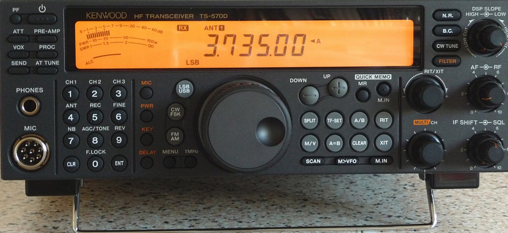
The rig is fairly chunky, measuring approximately 273mm back to front (excluding the additional depth of front controls and rear sockets), 285mm side to side, and 105mm top to bottom. The rig has a flip out metal stand which runs across the width of the rig, just underneath and slightly back from the front edge. This helps to slightly elevate the front of the rig and place its controls at a more ergonomic angle.
All the controls on this rig are on the front panel. The controls comprise a combination of tactile rubber buttons of different shapes and sizes, and plastic rotary dials. The controls are arranged into different zones, or groups. Although there are a lot of buttons and dials on this rig, they are sensibly organised and are relatively straight forward to distinguish by touch.
Towards the top left corner of the front panel is a cluster of eight buttons in two columns of four buttons.
The top left most of these is a small round PF (programmable function) button. This can be programmed to perform one of a range of functions. I have programmed this button on my rig to speak the RX signal strength via the VS3 voice chip. (This is achieved by changing menu 41 from a value of 51 to 52.) The remaining seven buttons in this cluster are all rectangular in shape. The first of these is the power button. This is located immediately to the right of the small round PF button, and it has a series of raised dots along its surface which make it easy to find.
The remaining six buttons in this cluster are as follows: buttons to activate VOX and send/receive, buttons to activate attenuation, pre-amp and processor, and a button to activate and tune the internal ATU. There is bleep feedback when these six functions are toggled on and off, the pitch of which is slightly higher when the relevant function is activated and slightly lower when it is deactivated. However, this difference in pitch is quite slight and so may be hard to detect reliably.
The ATU button is the one located at the bottom right of the group of eight buttons. Pressing the ATU button in and then quickly releasing it will toggle between turning the ATU on and off. You will want the ATU on unless you are intending to use an external ATU, in which case you will want it off; you should be able to tell whether it is on or off by the pitch of the bleep made when the button is pressed. With the ATU on, pressing and holding the ATU button in for a second or so will cause the internal ATU to look for a match. Whilst doing so, the ATU provides good auditory feedback through the sound made by the latching of the relays. If a match is found, there is a single beep. If a match is not made, then a longer sequence of CW characters is played. I do not know CW, but I understand from other blind ops that the CW spells out “SWR”. In any case, even if you do not know CW, the sequence of bleeps produced when no match is found is noticeably longer than the bleep produced when it makes a match.
Immediately to the right of this group of eight buttons, and stretching most of the way along the top of the control panel, is a smooth plastic area. This is the LCD display.
Below this group of eight buttons is a 6mm headphone socket, and below this is a standard Kenwood mic socket.
To the right of these two sockets, and below the LCD display, is the numeric key pad made up of twelve round rubber buttons. These have a slightly convex shape. They are organised like a telephone key pad in three columns of four, with the 1 key in the top left, and the 0 key bottom middle. There are four small raised dots on the 5 key making this easy to locate. The bottom left button is Clear, and the bottom right button is the Enter key.
Direct frequency input is very easy: simply press the enter key, enter the desired frequency (omitting the decimal point), and then press enter again. All key entries are spoken, including “enter” when the Enter key is pressed. The new frequency is also spoken after the second press of the Enter key. Pressing the Enter key twice in succession will cause the VS3 chip to speak the current frequency, which is very handy.
Most of the buttons in the numeric key pad perform secondary functions which are activated if they are selected without the Enter key having been pressed first. For example: the 4 key toggles the TX and RX between Antenna 1 and Antenna 2 sockets; the 6 key modifies the operation of the VFO control so that one rotation of the VFO is either 1kHz or 10kHz; and the 7 key toggles the Noise Blanker on and off. Unfortunately, the VS3 chip does not speak the status of these functions, and whilst these keys do issue a bleep when pressed, there is no difference in the pitch of the tone of the bleep to indicate whether a function is in one state or another, so it may not always be easy for a blind operator to determine this. However, with some trial and error, and use of lateral thinking, this can often be overcome. For instance, it will be obvious when toggling between Antenna 1 and 2 which you are on if you only have one antenna connected, or if you have two, if you disconnect one of them. Using frequency read out by pressing Enter twice will tell you whether your VFO is moving in 1kHz or 10kHz steps if you check the frequency before and after a single rotation of the VFO tuning dial. These days, One can even use on-line software defined radios accessed through websites to listen to one’s transmissions to try and determine the setting of other TX related functions.
Moving on, there is a further column of four round buttons to the right of the numeric buttons. These are smaller in size than the numeric buttons, but also have a convex shape. They are the transmit functions which are used in conjunction with the Multi Channel selector dial found towards the bottom right of the rig. From top to bottom, these buttons are: Mic, to set the microphone gain; Power, to set the TX power; Key, to set the internal keyer speed; and Delay, to adjust the delay between TX and RX when VOX is activated. These buttons produce a high tone when activated and a low tone when deactivated.
So, for example, to adjust the TX power, you press the second button down once, then use the Multi Channel selector knob to set the desired power level, then press the Power button again to store the change. The Power button produces a high pitch bleep when the power setting function is activated, and it issues a lower pitch bleep when storing / deactivating the function. The difference in pitch is significant and so will be easy for most people to detect. Unfortunately, the VS3 does not voice the power level (nor any of the other values which can be altered with these four buttons such as the microphone gain level). Nevertheless, it is possible to set power accurately, since the lowest power setting in the range is 5 Watts, the highest level in the range is 100 Watts, and the incremental change is always 5 Watts. So, to set power to 50 Watts, press the Power button once and listen for the high pitched bleep. Then turn the multi channel selector anti-clockwise at least 20 clicks. This brings the power level down to the minimum of 5 Watts. Then turn the Multi Channel selector nine clicks clockwise, which increases the power to 50 Watts. Finally, press the Power button again and listen for the low pitch bleep to confirm that the new power setting has been saved.
The main control to the right of this column of four buttons, is a large VFO tuning dial. It is easy to grip as it has a ridged and rubberised outer surface. On the front face of the VFO tuning dial, there is also a finger indentation. A torque switch is located at six o’clock directly underneath the tuning dial which, when slid to the left provides a light touch movement to the dial. When slit to the right, it provides greater friction in the movement of the VFO dial making it easier to move the VFO in very small increments. I like to have the VFO set to tune by 10 kHz per rotation, but this is adjustable as already indicated by pressing the 6 key which will reduce it to 1 kHz per rotation.
To the left of the VFO tuning dial and hugging the curve are a further three round buttons. These are slightly larger than the numeric buttons, but have a concave shape. These are the mode selectors, and from top to bottom they are: LSB/USB selector; CW/FSK selector; and FM/AM selector. When pressed, the VS3 chip announces the selected function in CW bleeps. This is not very helpful if, like me, you don’t know CW. However, I have learned to recognise the difference between LSB and USB because the CW bleeps for LSB are noticeably longer than the CW for USB (note that both “LSB” and “longer” start with the letter l, which is how I recall it).
Below these three buttons and still to the left of the VFO tuning dial are two very small round buttons (though I understand that on some versions of the TS570D these may be rectangular in shape). When pressed, they bleep, but there is no difference in the pitch to indicate what state they are in. This should not present any difficulties though, as we will see.
The right hand of these two buttons is the 1MHz / Amateur Band mode button. This button toggles the function of the Down and Up buttons between 1MHz and Amateur Band modes – I shall mention this again later.
The left hand of these two buttons is the Menu button. When pressed, the Menu button toggles the menu system on and off. Blind ops considering the TS570D will be pleased to know that the menu system is accessible via spoken prompts from the VS3 voice chip.
To activate the menu system, press the Menu button once. There will be a single bleep and the VS3 chip will announce the menu number, eg, “menu eleven”, and the state of the setting associated with that menu, eg, “on” or “off”. Once the menu system is activated, you use the Multi Channel selector dial to move up and down through the different menus, and each menu is announced by reference to its number. This means that one needs a separate list detailing what each of the numbered menus are in order to make sense of the spoken information. In order to change the setting associated with any given menu, one uses the Down and Up buttons, either on the rig itself, or on the supplied Kenwood microphone. I will discuss the Down and Up buttons on the rig shortly, but on the microphone, they are located on its top surface. The options within a menu do not wrap, so when the last option is reached at the start or end of a menu, further presses of the relevant Down or Up buttons will only elicit a bleep. Each time a menu setting is changed in response to a press of the Down / Up button, the new setting is announced, eg “on” or “off”. Again, one must refer to an external list detailing what the various settings associated with each menu are in order to make sense of this information. Once all changes are made, press the Menu button again, a short bleep is heard and the menu system is deactivated.
Thankfully, a list describing the numbered menus and their settings is provided in the manual, a recording of which is available on the Active Elements and RAIBC websites.
Moving to the right of the VFO tuning dial, there are four further groups of buttons. With the exception of the first and last of these, these are generally used for more advanced operation such as working split frequencies, and, not being a power user, I am less familiar with their operation. So my tour of this part of the rig will be less detailed.
The first is a row of four round, convex shaped buttons, located immediately below the LCD display. Working from left to right, these are as follows: the Down button; the Up button; the Quick Memory Recall button; and the Quick Memory In button.
The Down and Up buttons have a minus and plus sign, respectively, inscribed into their surface. Someone with sensitive touch may be able to make this out. These buttons perform three functions. As already seen, when the menu system is activated, they move down and up through the available settings within the selected menu. Otherwise, there other two functions involve moving the frequency of the currently active VFO: when the rig is in 1MHz mode, they move the frequency by exactly 1MHz; when Amateur Band mode is active, they move the frequency from one amateur band to the next.
The Quick Memory buttons provide a quick way of writing, and then recalling, operating settings into quick memory. There are five quick memory positions. Each time new settings are added to quick memory, the oldest entry drops out of memory and the remaining four entries are shuffled along one place to make way for the new entry, which is added into the number 1 memory position. Data that can be entered into and recalled from Quick Memory includes frequency and mode, as well as other settings. To add a frequency and its associated settings into quick memory, simply press the Quick Memory In button. This button has a tactile dot on its surface. It will bleep to confirm. To recall a frequency and its associated settings from quick memory, press Quick Memory Recall. There will be a bleep, and the VS3 will speak the number of the currently selected memory position, followed by the frequency stored there (it will not speak any of the other settings such as mode). Use the Multi Channel selector knob to click up an down through the five available quick memories. As you do this, the VS3 will speak the memory position and the frequency stored there, and the VFO will jump to that frequency so that the RX can be heard. At this point, a user has two choices. You can either exit quick memory and return to your previous frequency and settings by pressing Quick Memory Recall again. Alternatively, you can choose to exit quick memory and return to normal operation using the settings stored in the selected quick memory position. To do the latter, you need to press the N>VFO button (discussed below) instead of the Quick Memory Recall button. Pressing the N>VFO button causes the contents of the selected quick memory to be copied to the VFO and puts you there whilst also exiting quick memory. In either case, there will be a bleep to confirm.
The next group of buttons is below the row containing the Down/Up and Quick Memory buttons. This group is arranged in two rows of four round buttons. The buttons themselves are slightly larger, and are concave in shape. These buttons largely relate to split operation, which is not an area I have explored in any detail. I shall therefore skip over this section. However, I understand from other blind ops that it is possible to operate this rig in split mode, if that is something you are interested in doing.
The next group is a row of three rectangular shaped buttons immediately below the buttons used for split operation. From left to right these are the Scan button; the N>VFO button; and the Memory In button. The N>VFO button is used, as mentioned above, to copy the contents of a quick memory to the VFO.
The last group of buttons is a column of four rectangular shaped buttons immediately to the right of the LCD display. The top button is a Noise Reduction filter which toggles between three settings: off, and two filters referred to as NR1, and NR2. The next button down is a DSP beat cancellation filter which toggles between on and off. It is usually obvious from the RX audio whether these filters are activated. The next button down activates the CW zero beat function. The bottom button enables the RX bandwidth to be changed if an optional filter chip is installed, which it is not in my rig.
The remaining five controls on this rig are smallish plastic rotary control dials which are all easy to locate and use. The first two are located below the column of four buttons which I have just mentioned. The top one is the RIT / XIT dial which is used for split operation. The bottom dial, which is located at the bottom of the front panel, is the Multi Channel selector dial. This clicks as it turns. This makes the selection of frequency (when in VFO mode), menus (when the menu system is activated), and quick memories (when Quick Memory mode is activated) straight forward. Using menus 4 and 5 in the menu system, the Multi Channel dial can be set so that, when changing frequency in VFO mode, it does so in steps of 1kHz, and to the round frequency, for every click of the dial; this is a very useful setting to bear in mind.
At the extreme right hand edge of the control panel are three further dials which effect the RX audio. They are all designed with an inner and an outer dial which move independently of each other. The top dial is a DSP sloping pass band used to cut out high / low frequency noise. The middle dial is the RF gain and the audio volume. The bottom dial is the squelch, and the IF band pass control which enables you to slightly adjust the RX band pass higher or lower when interference is present. These are all perfectly usable by a blind op as their effect is obvious from the RX audio.
With the exception of the headphone and microphone sockets, all other sockets are located on the rear of the unit. I shall not discuss these as they are amply described in the manual, a recording of which is available on the Active Elements and RAIBC websites.
Three final observations will complete this accessibility evaluation of the TS570D.
First, just to make clear that whilst the VS3 provides spoken access to certain information such as the current frequency, the frequency in quick memories, and the menu system, it does not speak the status of other settings such as mode (although these are indicated using CW tones), filters, and other TX and RX settings.
Secondly, it is worth knowing that the TS570D retains the status of certain settings within each amateur band allocation. Settings being used for each band are stored independently of the settings being used in other bands. The settings that are stored are those which are set when the VFO moves in and out of the band, whether this occurs via direct frequency input, by turning either the VFO tuning or Multi Channel dials, or by moving via the Down and Up buttons. Therefore, if you adjust a setting, such as switching from LSB to AM, this will be retained when you return back to the band. This is the case even if you have powered off the unit and then powered back on. This clearly has advantages, but it can be a little annoying if a setting is changed inadvertently as it may take some time to realise that you have made a change and what that change is. I would suggest, therefore, adopting a fairly strict routine of trying to ensure that all settings are returned to an expected state before switching bands or powering off, in order to avoid unexpected surprises when that band is revisited, or the rig is switched on next time.
Third, whilst it is adequate, the sound quality from the internal speaker is not as good as you may wish, and therefore a separate speaker may be desirable. One of the nice things about the audio on this rig, especially when using an external speaker with an independent volume control, is that you are able to independently control the volume of the RX audio and the information spoken by the VS3 chip. The AF dial on the rig itself can be used to control the RX audio, but this does not change the volume of the VS3 announcements; to do this, you can use the separate volume control on your external speaker. When working with the internal speaker, or on headphones, the VS3 volume is set to a specific level which can not be altered, but I find that it is set to a perfectly acceptable level for my normal hearing.
Related Downloads
TS-570 MP3 Manual
TS-570 Front and rear panel layouts, and Menu system.doc


