WSRotor Accessibility Demonstration

White Stick Rotor Accessibility Review and Demonstration

By Kelvin Marsh M0AID

July 2013

This is an audio demonstration of the WSRotor software written by Don G0MDO. WSRotor allows a blind amateur to operate the ProSisTel D type rotator control box using a computer and screen reader.

The software can be downloaded from
http://www.easilog.co.uk/WSRotor.htm

Related Downloads

WSRoter MP3 Demonstration

PST 2051 Rotator Accessibility Review

Accessibility Evaluation of the ProSisTel 2051D rotator.

By Kelvin Marsh M0AID

July 2013

My first HF beam was a fairly lightweight 3 element Cushcraft A3S. I was fortunate to be given an old Kenpro KR600 rotator, and my friend G4JZL adapted the control box with a tactile pointer to show the heading. When I changed the A3S for the heavier 3 element SteppIR, it was time to beef up the rotator too.

At that time, back in 2009, I did not know any other blind amateurs with rotators. I was intrigued when I discovered that there were rotators available with computer control via RS-232 serial connection, and as I use a PC for logging and amplifier control, this seemed an intriguing possibility. I then had to satisfy myself the software could be used by a screen reader user. There was little point in investing significant sums in a new rotator that was controlled by clicking on a picture of a compass comprising of a large and inaccessible graphic!

I became aware of the ProSisTel range of rotators, as they were recommended by the UK supplier of SteppIR antennas. The PST 2051D was the recommended model for the 3 element SteppIR. The PST rotators use worm drives instead of the more traditional planetary gear wheel system, And have the advantage of being extremely sturdy and self braking. The PST 2051D is at the lower end of the model range, and PST has several much heavier offerings for very large antenna arrays. The PST 2051D is classed as a heavy duty rotator, capable of turning a full size 3 element HF beam. The rotation torque inch / lbs is 1720, and the braking torque inch / lbs is 10800 (figures taken from the Vine Communication rotator comparison table).

In a way, this evaluation is more of an accessibility review of the D type control box. Whilst I suggest this should be carefully checked before purchase, the control box should be capable of running any of the modern range of PST rotators.

The D type control box is the unit that sits in the shack, and is the hardware you would normally interact with. The box is very chunky, with an approximate height of 120mm, and a width and depth of 210mm plus front and rear panel protrusions. I only ever touch the controller when I switch it on. Whilst the control box is extremely simple to use with sight, it is not directly accessible by a blind amateur.

Photo of rotator control front panel displaying a bearing of 333 degrees, with switches for direction and power, plus a manual rotation control

Rotator control unit front panel

The current compass bearing is shown on a large digital display, and the new direction is selected by turning a rotary knob. The physical revolution of the knob bears no direct relationship to the ultimate direction. The sighted operator rotates the knob until the desired bearing is shown on the display. The knob could be rotated a few clicks, or could be turned completely several times, as there is no end stop.

Whilst I have noticed there can sometimes be a relationship between the clicks of the rotary knob and the heading for small movements, there is no reliable control possible.

Usefully, the rotator has the ability to automatically decide on the direction to turn. Just a small alteration in direction can cause the rotator to turn clockwise or counter-clockwise, to reach the desired heading with the minimum of movement. This probably sounds counter intuitive, until you understand the rotator has the potential to overlap by up to 70 degrees on either side of the selected stop position.

This probably needs a note of explanation. The rotator can be setup with a North or South stop position, and with a choice of turning ranges. Firstly, the rotor can be set to only turn by one complete revolution or 360 degrees. Secondly, to have up to a 70 degree over-lap either side of the stop position, giving a potential 520 degrees of movement. I use a 20 degree over-lap on either side of the stop position myself, so as not to overly strain the coax.

Here in the UK it is much more usual to be pointing the beam towards the South, so I decided to have a 0 degrees North stop. This means the rotator can be turning in a clockwise direction from 290 degrees West, through 0 degrees North, 90 East, 180 South, 270 West, 0 degrees North, and then keep on turning clockwise passed the North position, to a maximum of 70 degrees East. All this sounds complicated, but in reality it means you don’t have to turn the beam by almost one complete revolution, if you are wanting to point the antenna a few degrees either side of North.

So, back to the sighted operator directly using the control box. They just turn the knob to the desired heading on the digital display, there is a pause for a few seconds to allow for changes, and then the antenna turns. The control box automatically decides which way to turn to get there in the shortest time possible.

The 2051D control box also has the traditional Clockwise and Counter-Clockwise paddle switches. Again, these are of no real use to a blind operator as the display cannot be read. There is mention in the manual of the paddles being used to halt the rotator if it has been preset with the rotary knob or computer software, and there is also a warning that turning the rotator using the paddles does not invoke the slow start and stop facility.

When I first bought the rotator we set it up on the ground, without the antenna being attached, and I experimented with it. It soon became apparent that the slow start and stop feature only worked if the heading was changed using the inaccessible rotary knob, or by using computer software. If you are turning a large heavy antenna, it is highly recommended that you always use the slow start and stop. This causes the rotator to gradually reach the maximum turning speed over a few seconds, and minimises the shock to the antenna and tower of an instant start and stop.

In this photo the tower has been tilted over and the rotator is being bolted to the cage on the tower.

Close up of the rotator during installation

Therefore, the only practical method of a blind operator controlling the PST rotator, is via the PC and the serial interface. If you don’t use a computer with your amateur activities or want to directly move the antenna using the control box, it will be worth reading the Yaesu G1000DXC rotator evaluation elsewhere on the Active Elements site.

As mentioned previously, I initially had concerns regarding the accessibility of any interface software. Any blind computer user will be familiar with the perils of buying and installing that vital program, the one used by all of your sighted friends, only to find that what can be done so easily with a few mouse clicks, is impossible with a screen reader. It was at this point I contacted Don G0MDO. Don has written a very accessible logging program for blind operators, and fully understands what screen reader software needs to work successfully. Studying the PST documentation, it seemed that third party software could be used to control the rotator, and when approached, Don G0MDO, the creator of White Stick Log, began work on White Stick Rotor.

I know Don had to jump through all sorts of programming hoops to write White Stick Rotor, and had to write simulation software to mimic the PST D type control box itself. At that time, neither Don or myself owned any PST hardware! We were fortunate to have the help of Ron at Vine Communication, who was happy to conduct some tests On a real control box.

Without doubt, White Stick Rotor was the last piece of the jigsaw, and gave me the confidence to buy the PST 2051D. Over the years, Don has continued to refine WSRotor, and perhaps there is still some improvement to be made. The software is beautifully simple to operate, and Don has even made itself voicing. There is an audio demonstration of White Stick Rotor on the Evaluations page in the Software section. Suffice to say, you type in the desired bearing, press Enter, and the antenna turns.

Subsequently, I have also used the N1MM contest software to control the PST 2051D. The program can be used stand alone, but is also able to automatically turn the rotator to the bearing of the callsign just entered. I cover the N1MM rotor setup and use on the Evaluations page.

This photo shows the rotator mounted in the cage at the top of the tower

Rotator finally installed.

Finally, the rotator is designed to be fixed inside a rotator cage. The manual warns against sitting it on a surface that is likely to collect water, as this can be drawn up through the drainage holes in the casing. There is a sturdy circular revolving table on the top of the rotator with fixing holes, and there are a variety of mast clamps available to mount the stub mast.

A close up photo of the specially made adapter. Part of this fits inside the stub mast and is anchored to it. The remainder is bolted to the rotator.

Close up of the machined adapter

The best solution for me was to have a mounting plate with a solid shaft custom machined by G0WSC, to bolt to the table and to fit up inside the stub mast. The stub mast is then secured to the shaft and plate with a pin. This solution means that as the table revolves, the stub mast is perfectly centred and there will never be any slippage due to loosened clamps.

Related Downloads

PST D type rotator MP3 manual.zip

Kenwood TS-990 Accessibility Review

Accessibility Review of the Kenwood TS-990

By Kelvin Marsh M0AID

July 2013

It’s not often that one of the main amateur radio manufacturers launches a new flagship model. When Kenwood announced the TS-990S it naturally caused great interest, and I was intrigued to learn the radio would include an integral voice unit. Other recent Kenwood models can be fitted with the optional Voice Guidance and Storage unit, the VGS-1, and the built-in voice guidance might mean there was an improvement to accessibility, or might mean a reversion to former more basic functions. As you read on, you’ll see I was extremely impressed by the work done by Kenwood, and the TS-990S has made huge accessibility leaps forward!

TS990 on the desk with matching speaker, and a Kenwood mug, for those long QSO's

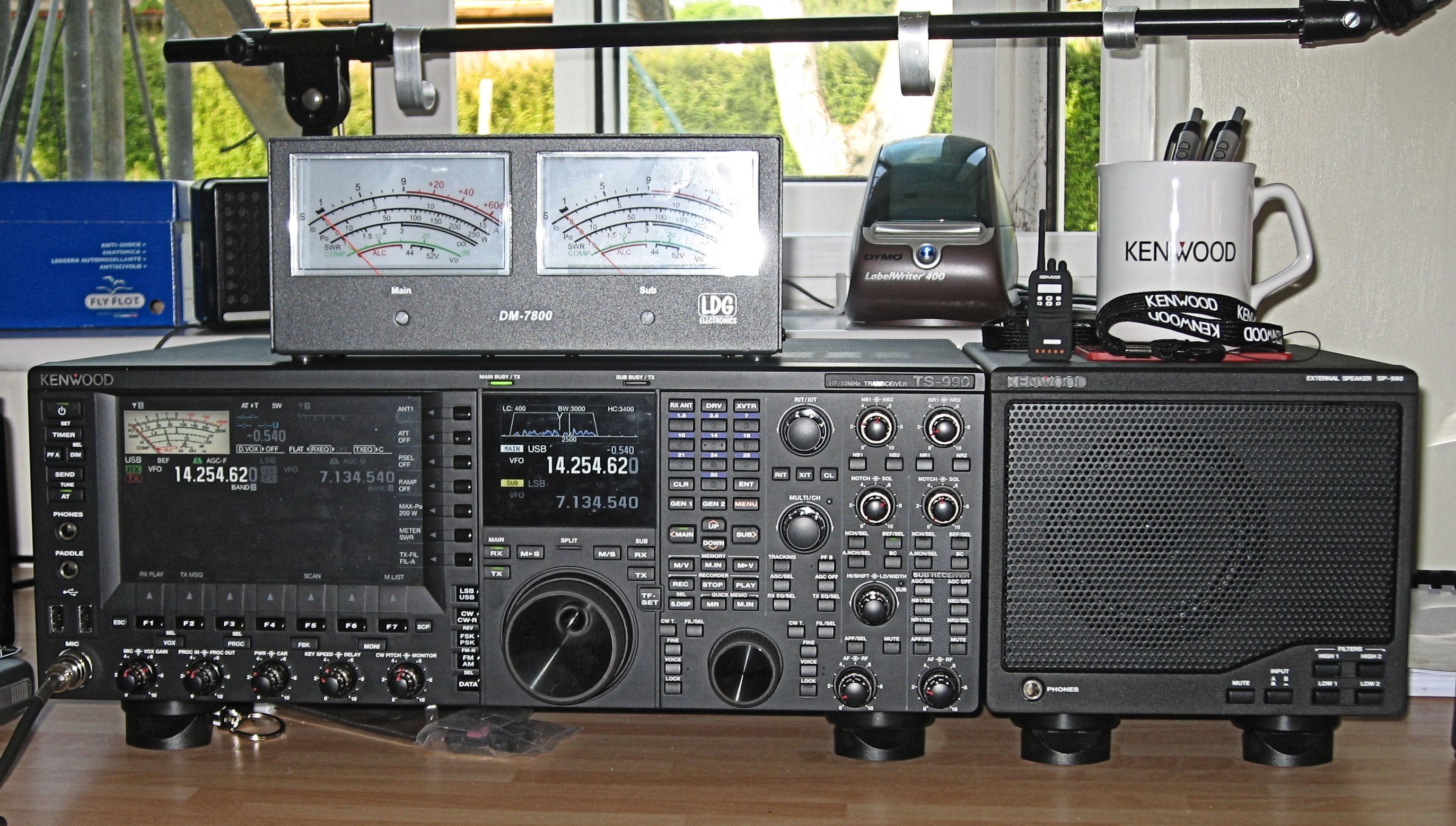
TS990 + SP990 + DM7800

The Radio

The TS-990S is a large 200 watt base station, allowing transmissions on HF and 6m. It has an integral ATU, and is mains powered. It has connections for 4 TX antennas and an RX antenna. I measured the size of the casing to be approximately 460mm wide, 160mm high, and 400mm deep, excluding front panel controls. The feet add about 40mm, making the actual height more like 200mm. This is an imposing radio!

It is sadly inevitable that much that the TS-990S has to offer will be unused or unappreciated by a blind operator. The radio has large vibrant displays, and these caused quite a stir from several of my sighted friends. The TS-990S has many data decoding options and display graphics, and I spotted in the manual it can even be used for logging, using a USB keyboard.

There are varied alternatives for getting audio into and out of the radio, and as well as Ethernet, USB and serial connectivity to a PC, both optical input and output is available, along with USB drive storage.

Undoubtedly, one of the prime attractions of the TS-990S is the ability to have two independent cross band receivers. Anyone who seriously works DX, will immediately understand the advantages of listening simultaneously to the TX and RX frequencies of the DX station.

I think that if you want to know more about the radio’s capabilities, you would be wise to read the full technical review by Peter Hart in the June 2013 RadCom. This is available in MP3 format in the Related Downloads section below.

This evaluation is looking solely at accessibility, and how the TS-990S can be used by a blind operator. I am very grateful to Kenwood Electronics UK for the loan of the review radio.

First Impressions

My first impression of the TS-990S was somewhat daunting! There are lots of controls, but it soon became apparent that Kenwood had brought all of the commonly daily used controls onto the front panel. Whilst initially overwhelming, it didn’t take long to realise I recognised every control, and they all made sense. This radio is geared up for quick and seamless operating, and while there is undoubtedly a learning curve, you won’t be digging into the menus just to increase the power.

As previously mentioned, there are two displays. The largest is positioned on the left at the top of the front panel, the smaller is approximately in the centre top with the main tuning VFO below, and the right third of the front panel is given over to button and rotary controls.

All of the buttons are a hard flat plastic, meaning there is no unpleasant dragging on the finger tips as you feel for a control, and the buttons are flat and without lumps and bumps. There are many different shapes and sizes of button, and it will take some time to become fully accustomed to their layout. In fact, I think the manual will almost certainly become your best friend, for a while at least!

Layout

In slightly more detail, there are buttons in a vertical column at the far left of the facia, and to the left of the large display. These include The power on, Timer, Programmable Function A, Send, and Auto ATU. There are 7 function keys running along the bottom edge of the main display, and a series of rotary knobs below the function keys. These are typical concentric inner and outer rotary knobs, and control Mic and VOX Gain, Processor levels, TX power levels, Key speed and Delay, and CW pitch and Monitor level. Just above and in-between these knobs are 4 further buttons related to the function of the knobs themselves.

A vertical column of 7 buttons is positioned between the displays, and they include control of Antenna selection, Pre- amp, TX power limits, the display Meter, and TX filter. Below this column are the vertically arranged Mode buttons announced with CW, and to their right, the main tuning knob.

To the right of the smaller display and Main tuning dial, at the top, is the numeric keypad, with markings on the 5. This has 3 buttons above including RX antenna selection, and transverter, and the Menu button is in the row below the keypad. Below this is the main block of buttons. These include Main and Sub band selection, with Up and Down buttons in a group. A group of 9 buttons operate the Memory system, RX record and play back, and Quick Memory.

There are 6 buttons in 2 groups of three, positioned above and either side of the main tuning knob, controlling the use of the two receivers and the Split function. There is a column of buttons to the right of the main VFO for Fine tuning adjustment, Main Voice, and main Lock. Continuing to the right along the bottom of the front panel is the smaller Sub tuning dial, and the Fine, Voice, and Lock are mirrored for the Sub receiver.

Moving to the top of the facia and to the right of the keypad is the RIT adjustment knob, with related buttons below. Below this is the Multi-Ch control, with 2 columns of 3 buttons below, for Diversity reception, PF B, AGC, and RX and TX Equaliser. It is nice to find the equaliser controls have found a place on the front panel. Below these buttons is the previously described Sub tuning VFO.

Back at the top and to the right of the RIT, are inner and outer rotary controls for Noise Blanker 1 and 2, and then Noise Reduction 1 and 2 in the top right corner. These are turned on with buttons below each knob.

Below these, and to the right of the Multi-Ch control are inner and outer rotary controls for Main Notch and Squelch, and Sub Notch and Squelch. Below these controls are buttons to control the Notch behaviour on each receiver.

Below the Main Notch knob is the band pass control. a rotary concentric inner and outer knob allow the band width to be changed.

To the right of the band pass control are 8 further buttons to control the AGC, Noise Blanker 1 and 2, Noise Reduction 1 and 2, and APH, for the sub receiver.

Finally, the bottom right corner has separate concentric inner and outer controls for main and sub AF and RF gain.

For a comprehensive front panel layout, see below in the Related Downloads section.

A note on the layout. Make no mistake, this is a complex radio! There is a large block of buttons extending below the keypad, and my sighted friends initially expressed some concerns that none of the button groups lined up with their neighbours. In reality I’ve not found this a problem, but the button area is busy. I think that having a varied tactile layout can aid navigation, and as I’ve become accustomed to how everything fits together, I’ve found the different shapes and positions actually helps me find the needed control. The manual is currently available in PDF format, and I found it quite easy to use with the Window-Eyes screen reader, and it is essential reading to understand the TS-990S operation. As a blind user, you will certainly also need a full front panel description in the learning stages.

One small criticism about the numeric keypad, I personally don’t feel there is enough space around it for rapid tactile use. There is a row of 3 keys directly above and below the keypad, and only the slightest increased separation between them. I can’t help feeling that over the course of the radio’s life, a blind user will potentially use the keypad thousands of times and very swift operation is only possible once the first button press has been verified as correct. Saying that, the keypad is fully voiced, which is a tremendous asset.

Preparations

The TS-990 has the integral automatic announcement voice guidance switched off by default. As a blind user, you will want to turn it on. This can be done through the menu system, but the easiest method is to hold the PF A button when the radio is switched on.

Kenwood have been able to loan me the radio for just over a week, and I will be the first to admit the rich feature set of the TS-990 will need much longer to investigate fully. I discover something new in terms of accessibility every time I switch on the radio, and you will understand why as you read on.

Traditionally, amateur radios have been made accessible by announcing button presses, and announcing the result of any changes. The TS-990S does not slavishly follow this convention, but has taken huge strides in accessibility by giving spoken announcements to the changes being made on the displays through the Function keys. This means that even the very advanced options, such as recording audio messages, can be easily managed by interacting directly with the display a sighted operator uses!

I normally write about the great Kenwood accessibility to the menu and memory systems, and all of this is spoken as we have come to expect from Kenwood, but we are not used to having such accessibility to the more advanced functions of high end radios. The TS-990S, in my opinion, has moved the game forward in leaps and bounds.

It seems to me that the traditional menu system is now more reserved for adjusting little used settings, the kind of options you set and forget. All of the more commonly used features have either been given their own control on the front panel, or are adjusted on the main display using the Function buttons running along the bottom of the display. I believe it is this accessibility to using the Function Keys that really sets the TS-990S apart.

Once I had started the automatic announcement of the Voice Guidance, by switching on with the PF A key held, I decided to install the Kenwood ARCP software on my PC. This is free from the Kenwood site, and it immediately gave me access to the menu system via the PC, using my screen reader. The Menu is accessible using just the radio, but only the menu numbers are spoken, and you will need an external list of the menu structure to browse through it successfully.

The big advantage of using the ARCP software is that it is accessible, and each menu option is described. I’ve not actually spent much time investigating the software, but the pulldown menus seem to work well, and it seems to me this is certainly an easy way to make Menu changes. Any changes made using the ARCP are immediately seen on the radio, and similarly, any changes made to the menu on the radio were immediately seen on the PC.

Using the software, the Menu is shown as a Tree-View, and each group is then opened to show the options. When you want to make a parameter change, just tab through the Checkboxes.

If you use the rig to make menu changes, just press the Menu button, move through the options with the Multi-Ch control, and press F4 to select. The use of the F4 function key, as the selection button, was my introduction to using the function keys.

As is my preference, I was able to set the Multi-Ch control to 1kHz steps for each rotary click, and the frequency is moved to the round figure. This means I can tune for a signal, and providing it is on a round frequency such as 7.106.00, I can make the final tweak with the Multi-CH control.

I also like the VFO to move by 5kHz for every complete revolution of the main VFO, and this was easy to set. When the Fine frequency button was engaged, each revolution then moved by 500 Hertz, meaning I would move from 7.100.00 to 7.100.50. I was also very pleased to see the frequency was announced to the Hertz level with the Fine adjustment engaged. The frequency is announced as 7.100.500.

Operating

Over the course of the evaluation I found that visits to the Menu were very infrequent. As I’ve previously mentioned, all of the common functions of the radio are controlled from the front panel. I found that when I needed an announcement I got one, and when the voice would have been obtrusive, I got useful beeps.
I guess the Antenna change button and the Attenuator buttons sum up this approach. These buttons are in the column between the displays. Press the top button for aerial selection, and you hear ‘Antenna 2’. Subsequent presses give ‘Antenna 3’ and so on.

Move down to the Attenuator button and you hear one high pitched beep for 6dB, two beeps for 12dB, three beeps for 18dB, and a single lower tone for off. Holding the button takes you in the reverse direction.

The third button in the column is the Preselect. This button Beeps for on and off with a momentary press, and when held it announces the setting, and can be adjusted with the Multi-Ch control or the function keys. F1 held, will reset back to default.

MP3 Demo of Antenna Attenuator and Preselector keys

The fifth button in the column, the TX Power Limit button, allows you to set power limits on each band, and between data, non data, and Tune.

MP3 Demo of Power Limit Setup

The TS-990S has many options for assigning programmable function buttons. There are two dedicated buttons on the front panel, labelled PF A and PF B. By default, the PF A key announces incoming signal strength, or outgoing power when sending RF. PF B works in conjunction with the Meter button, and can announce Power and SWR when transmitting.

The Up and Down buttons on the microphone can also be assigned as PF keys, and an external unit can be constructed for eight additional PF keys. The optional MC-47 fist microphone has 4 extra buttons available for programming, and I calculate this would give the dizzying possibility of 18 programmable keys. As so many functions can be assigned to a PF key, this gives lots of options to move commonly used keys to somewhere more easily accessed.

Traditionally, the frequency announcement itself has been assigned to one of the available PF keys, but the TS-990S has two dedicated Voice buttons for both the Main and Sub receivers, so the PF keys are not needed for frequency announcement.

Continuing with our look at the vertical column of buttons between the displays, the sixth button, the Meter selection, is a pleasure to use. Among the options, the SWR, ALC, and Power are announced by transmitting RF and simultaneously pressing the PF B button. On the Meter screen, Processor is only announced if the Processor is enabled.

MP3 Demo of PF keys

I found the lower left row of rotary controls very easy to use, as although there is no voice announcement on the majority of them, the notch in the control can be felt. If we look at the first knob, the inner is the Mic Gain, and the outer the VOX Gain. Using the adjacent button gives access to the VOX Delay and Anti Vox setup on the display. Changes are made with the function keys.

MP3 Demo of VOX Setup

Split operation is very slick, with a dual watch function allowing the Main and Sub RX to be separated into left and right ear pieces. I needed to enter the menu to set the 50/50 balance for the headphones. All of the Main and Sub functions work very well, and Split operation is clearly announced.
A momentary press of the Split key announces ‘Split On’.

Holding the Split key announces ‘Split Enter’. If you then press a 5 on the keypad, the Sub receiver is instantly set 5kHz higher. If the Main is set to 7.100, you hear ‘Split TX 7.105’.

MP3 Demo of Split Operation

As we have come to expect with Kenwood radios, the memory system is accessible. As well as storing Simplex frequencies, using the F6 key when storing, Will allow the Sub band to be included. When subsequently scrolling through the memory channels, the duplex channels are announced with a ‘D’, and simplex channels with ‘S’.

The TS-990S has 6 channels to record voice messages. The messages are controlled using the function keys, running along the bottom of the main screen. Again, these buttons give enough spoken feedback for operation without sight.

To record a voice message press F2, you will hear ‘Voice Message’.

Press and hold F2 through F7, which corresponds to message channel 1 through 6. If you press and hold F2 for message channel 1, you will hear ‘Record Mic’. At this point you can change the input source, but the default is mic.

Press and hold F4 and make your recording. If you press F2, your message is played back.

MP3 Demo of Audio Messages

Setting the CTCSS tone is a good example of the TS-990S accessibility for lesser used features. Firstly, change the mode to FM, and press and hold F4. You will hear ‘Main Tone 88.5’.

Next press F6 to select the Main or Sub band. You will hear ‘Main’. F6 now toggles between Main and Sub.

Use F2 and F3 to switch between Tone and CTCSS, and use F4 and F5 or the Multi-Ch knob to move between the frequencies.

Press Escape when you’re done, and remember that holding F1 resets back to the default.

MP3 Demo of CTCSS Setup

Recording communication audio. You can record a maximum of 30 seconds of audio data per file to internal memory or a maximum of 9 hours of audio to a USB thumb drive. I found the Record, Stop, and Play buttons allowed me to capture received audio, and replay it instantly. Pressing F1 announced ‘Audio file’, and I was able to move through each of the previously recorded clips and play them.

AGC. The AGC buttons are available for both the Main and Sub receivers. There are full announcements for Fast, Medium, and Slow, along with their values. Holding the AGC button enters the AGC setup, and the values are easily adjusted and saved.

MP3 Demo of AGC Operation

I’ve mentioned the memory channel system is fully accessible, and the quick memories work well too. Interestingly, pressing Enter, and then rotating the Multi-Ch control, takes you through the history of frequencies entered through the keypad. A very nice touch, and again all announced.

Briefly, I found the Timer functions were announced, and while I did not complete the setup, programming the clock and setting a sleep timer all looked to be accessible. There is a Lock key for each receiver, and similarly two Mute buttons. Very usefully, I found the radio would announce its status at switch on, if it had been left in setup mode, or in Split mode, when it was switched off.

Conclusions

In summary, I am incredibly impressed with the accessibility built into the TS-990S. It seems the voice announcements allow the operator to make almost any change, as a sighted user would. I installed the ARCP software and this meant I could browse the menu system with descriptions, but whilst useful, it is not strictly necessary, as the menu plays a more minor role in this radio. Having the radio for just a week meant there is much more to discover, and no doubt much better ways of doing things, but I’m sure the audio demonstrations will give you a good idea of the tremendous work that has gone into making this radio fully accessible. Congratulations to Kenwood, for a flagship radio with truly superb accessibility!

Related Downloads

TS-990S Front Panel Layout.doc
TS-990S MP3 Recording of the June 2013 RSGB RadCom Review by Peter Hart
This article is © of the Radio Society of Great Britain (RSGB) and was originally published in their magazine, RadCom, 06 2013. It is reproduced here with their kind permission. For more information about the RSGB please visit http://www.rsgb.org.

Kenwood TM-V71E Accessibility Review

Image of TMV71E with detached head and microphone on top of radio.
Accessibility Evaluation of the Kenwood TM-V71E

By Kelvin Marsh M0AID

June 2013

The Kenwood TM-V71E is a mobile VHF and UHF transceiver for FM communication. There is not a terrific choice available for a blind amateur in this market with accessibility, and if you want a multi-mode radio, your best bet is probably one of the so called ‘shack in a box’ transceivers that also covers HF.

The TM-V71E has been around for several years, and is considered to be near or at the top of the shopping list for blind amateurs wanting a 2m and 70cm FM radio. Although generally accepted as one of the most accessible radios in this market, I thought it would be worth evaluating the TM-V71E, and I thought it was useful to jot down some of my findings.

I don’t intend to write a full review, and I am delighted that there are so many accessible resources available to get you started. Under the Related Documents section on this page are an MP3 review and demo by David 2M0TSR, the full manual recorded in MP3, and the full manual in HTML format. Each describes the layout and operation, and I would encourage any owner to check them out.

I have evaluated the TM-V71E, and this is the European version. I believe the other versions are very similar in operation, but with frequency allocations more appropriate to their region.

As I am almost entirely an HF operator, I was initially surprised by the small size of the TM-V71E! I’ve approximately measured the width to be 140mm, the depth 190mm plus front controls, and the height about 40mm.

The radio has one N type antenna socket, computer and TNC sockets, and will support two external speakers, one for each VFO. It transmits on 2m and 70cm, and has three power levels. Low is 5 watts, Medium is 10 watts, and High is 50 watts. There is no numeric keypad on the front panel, but the chunky microphone has a keypad, and 4 additional programmable buttons. The radio can also be used to receive frequencies outside of the amateur bands in FM and AM modes.

The front panel controls are very well defined, and the buttons are a hard plastic giving no finger drag as you move from control to control. There is a small tuning knob at the bottom left of the facia, And this clicks as you tune through the frequency steps. This knob is also used for selecting memory channels and moving through the Menu. The bottom right has two Volume and Squelch knobs, for independent VFO a and VFO B control. These knobs and the Tuning knob can also be pressed for additional functions.

The test radio was fitted with the optional VGS-1 voice guide. This gives spoken access to the majority of button presses, but I must stress that there is still a need to read and understand the operating guide, as the radio is surprisingly complex in use, and there are several potential pitfalls just waiting to trap the casual blind operator .

The Memories are spoken, giving accessibility to the storage of repeater programming, and the Menu system can be navigated with speech output. In line with other Kenwood radios I have tested, the Menu channels are not fully described as you move from item to item, and it is necessary to have an external reference list at hand.

Menu access is achieved by pressing the Function key followed by the Tuning knob. You are given the spoken prompt ‘Menu 001’, and further turns of the Tuning knob click through to ‘Menu 002’ and so on. As you move through the menu, the selected parameters are not automatically spoken for each menu. I found I had to press the Tuning knob to be placed into a talking list of the parameters. A further press of the Tuning knob saved the setting, and returned me to the menu list.

Using the microphone keypad, it is very straightforward to enter a direct frequency, but first, one of the Programmable Function (PF) buttons must be designated as Enter. I found that it was ideal to use one of the four PF buttons on the mic for this purpose, and menus 509 to 512 can be used to set these buttons. I found the PF keys seem to be programmed in the reverse order to my expectation. For example, 512 is the top PF button on the mike, and 509 is the bottom button.

The tone key cycles through Tone, CTCSS, or DCS, and Off. These functions are not initially spoken, and each setting has the same higher pitched beep, with the Off position having a lower beep. I also found that when on the CTCss and DCS positions, the radio usefully became silent, as only signals with the appropriate coding are allowed through. I guess this might cause some head scratching if the tone button is pressed accidentally.

If I needed to set the CTCSS, I pressed the Tone button until I heard the lower pitched beep of the Off position, pressed a further two times, and pressed function. Now, a further press of the Tone button would speak ‘CTCSS frequency 88.5’. The tuning knob is then used to make the selection, and a further press of the Tone button saved the setting.
In its simplest operation, I found the Rev key worked by switching the input and output frequencies when listening to a repeater. I briefly investigated the more advanced Rev functions, and I could change the plus or minus offset frequency. Pressing Function followed by Rev toggled the settings between Off, minus, and plus. The Off position, where there is no offset, gave a low pitched tone, and plus and minus gave a higher pitched tone. At each stage I pressed VFO A volume control to read the frequency, in conjunction with the Rev key, to find out what I had changed. There is plenty of scope for confusion using this function, and I suspect there will seldom be a need to use it beyond initial setup, and possibly never.

Here in the UK, the 2m repeater outputs are in the frequency range 145.600 to 145.800. I found that entering a frequency in the repeater block automatically set the correct offset for the transmit. It is then just a matter of selecting the right CTCSS tone and saving to memory.

As we have come to expect from Kenwood, the memory channels are fully accessible. The channel numbers are spoken and their status is announced. If you have lots of repeaters in your area, it would be useful to maintain a list of frequencies and the memory channels used. There is a facility to label memory channels, and while the actual labelling process was inaccessible, I did add one label, with sighted help, to see what happened. Unfortunately, only the channel and frequency were spoken, the tag was ignored.

Since I started to evaluate the radio, I was intrigued by the voice announcing ‘PM2’ at the power on. Investigating further, the radio has 5 Programmable Memory states. This allows a single user to setup the radio for several types of operating or for use in different localities. It also means that several different users can tailor the functions to their particular preference, and store the individual setup.

This system is again accessible, but I think could cause a degree of confusion if the wrong buttons are pressed. Imagine setting up the PF keys on the microphone in PM1, and then accidentally moving to PM2. All the settings still reside in PM1, but appear to be lost.

With this scenario in mind, the way of changing the PM status is as follows. Simply press the PM button until ‘PM’ is heard, and then press one of the keys running along the bottom of the front panel. The Call key turns PM mode off, the Function key moves you to PM1, the tone key to PM2, and so on.

The memo and conversation functions of the VGS-1 work as described in the manual, and can be easily used.

Unfortunately, I could find no way of having the VGS-1 tell me the incoming signal strength.

Overall the Kenwood TM-V71E is highly accessible, but there are still some areas where the blind operator has to infer the information, rather than being told it explicitly. I am personally surprised at the complexity and rich feature set of this small VHF and UHF radio, and it is certainly a unit where the manual needs to be read thoroughly. Once again, Kenwood have worked extremely hard to make the TM-V71E very accessible through the VGS-1 voice guidance system.

Related Downloads

Kenwood TM-V71E MP3 Audio Review by David 2M0TSR
TM-V71E Full MP3 Manual (Please Right click and Save Target As:
TM-V71E Full DAISY Manual (Please Right click and Save Target As:
Rob K6DQ has prepared a fully accessible HTML manual, and related files
Kenwood TM-V71E K6DQ files
Download and unzip this truly excellent file containing a fully indexed HTML web page giving links to the text and descriptions of the user manual
The K6DQ file also contains:
Kenwood TM-V71E HTML Menu description
Kenwood TM-V71E TXT Microphone Keypad Description
Kenwood TM-V71E TXT Front Panel Description
Handihams have, at the time of writing, the following files and audio tutorials in their Manuals section:
tmv71_layout.mp3
tmv71a.mp3
tmv71a_brochure.txt

Ham Morse iPhone app Accessibility Review

Ham Morse iPhone app Accessibility Review

By Deborah Armstrong, KF6BKR

June 2013

Ham Morse is very accessible. I’ve reviewed it on applevis.

http://www.applevis.com/apps/ios/education/ham-morse

I use it in conjunction with the G4FON Koch trainer; this one is easier to carry

in my purse! G4FON gives you more practice in real-world conditions. This app is

better if you are trying out different learning methods as it supports them all.

One important point: if you choose the Koch method with this app, the add and remove

character button labels are reversed. So choose remove to add a new character and

you’ll do fine.

Take Another Stab at CW G4FON Accessibility Review

Take another Stab AT CW

By Deborah Armstrong, KF6BKR

June 2013

Are you one of those who waited to get your general or extra after the code requirements were dropped? Or are you like me,an advanced who plateaued somewhere around 15WPM and just couldn’t seem to get beyond that speed?

Or perhaps you used to copy fairly fast, but now the skill is rusty.

Of course, many of us have no desire to learn CW and that’s just fine. There is a place in ham radio for a variety of avocations.

But suppose being a high-speed CW OP appeals to you. Noticing all the noise on the bands lately, I wanted to grab a pee-wee antenna and climb a mountain to get away from it. But phone QRP is not as exciting as using code, and CW is the only thing that’s really going to punch through all that noise. Those of us plagued with local antenna restrictions might view CW as a way to enjoy operating under the radar.

Besides, I wanted to understand beacons or even a repeater ID without struggling to copy the faster transmissions. And sometimes, hearing a strong CW QSO on my shortwave, I was just so curious about what those two hams were ragchewing about. And of course, I’d love to expertly operate those accessible rigs with CW frequency and menu readouts!

To master CW, we’ve been told that all we need to do is practice, and surfing the web, we discover that multiple learning ideas and tutorial software abounds. We can purchase or run free applications on most any computer, including our smartphones. We can buy the pocket Morse code trainer from MFJ, or use old-fashioned tapes. I even bought a set of old Morse code training records for a buck at a swap meet.

I attempted to practice with many offerings, and was still stuck on my plateau. As a blind ham, I felt kind of embarrassed, as many of my other visually impaired friends took to code like a duck to water. I also found much of the tutorial software inaccessible; I memorized the tapes and records and even though I walked around silently repeating dits and dahs to myself, as soon as the speed of others’ code shot up, I was five or more letters behind trying to copy.

Ray Goff, G4FON, and Dave Finley, N1IRZ had the same problem. Though accomplished tinkerers and communicators, they too had despaired of learning the code, despite attempts to practice using a variety of methods. When I discovered how they’d succeeded, I knew I’d found my solution.

Many methods are based on having you build a look-up table in your head; three dits is an S, 4 dits is an H. Farnsworth spacing gives you enough time to rapidly search that table to copy each character, before the next is sent.

Lugwig Koch, a German psychologist in the 1930s, felt that learning code this way was all wrong. He suggested we learn CW at the high speed in which we ultimately intend to copy so we never develop the limiting habit of searching that mental look-up table. His Koch method trains your reflexes by starting first with just two characters, and after you’re able to copy them with 90% accuracy, you then add a third character. Progressing at your own pace,you can copy characters, digits and prosigns, whole words, and eventually entire conversations in your head. And you learn this all at rapid-fire speed!

The Koch method is rewarding because you are always copying fast code. It motivates practice, because success is immediate. You work at a pace that is individualized for just you, learning what you can, when you find the time. The only real requirement is that the practice should be regular.

It doesn’t take talent or a good ear, or any special ability except the willingness to drill. Dave was so taken with the Koch method he wrote several articles on, and single-handedly revived the technique. Back in the 1930s, Koch’s research had been a curiosity as it was impractical to implement. To achieve his successes of teaching volunteers in 12 hours to copy all characters at high speeds, Koch needed human operators who could repeatedly drill his subjects. Dave realized today computers can do that, so he wrote “Morse Code: Breaking The Barrier” which was published by MFJ. In this book, Dave explains how to configure Morse tutor software for the Koch method. And of course, the MFJ-418, their pocket tutor can also be configured for Koch.

But I find the MFJ-418 mostly inaccessible, because its layered menus are difficult to memorize. When I asked on the blind-hams Internet list for thoughts about accessible software, the clear recommendation was to use the Koch trainer written by Ray, G4FON.

Ray’s Windows software works with JAWS, NVDA, Window-Eyes, System Access and SuperNova. I’ve tried it with them all. I also tried it under both Windows XP and 64-bit Windows 7 and Ray claims it works all the way back to Windows 95. And because it’s already set up for the Koch method, you don’t need to change the number of characters, or the order in which they are presented. Best of all it’s free.

The Koch trainer screen’s layout keeps most options in view. There are only two items on its menu bar, file and About. Under about, there’s a single help screen. Under file, you can choose to record the audio it sends in MP3; you can exit help or call up a single dialog box for Setup. It’s really not necessary to fool with the setup at all.

Under the menu bar, there are clearly labeled icons, toolbar buttons for Start, Stop, Setup and Finish. Setup takes you to the same configuration dialog you could access from the File menu. Start and stop begin and halt a training session. Finish exits the program. You can click directly on the graphics or on their corresponding labels below them. You can use a screen reader’s graphics labeler to label the graphics too, though that’s not necessary, since clicking on the onscreen label also activates the button.

Though there is no keyboard access to these buttons, a helper program, discussed below, will give you all the keyboard access you need. If you hover over one of the toolbar icons with the mouse, its corresponding label is also highlighted, making it very easy to use even for those who are not computer whizzes.

The remainder of the screen is a grid filled with controls, which can be clicked on or accept focus by repeatedly pressing TAB or SHIFT-Tab. These are spin boxes, radio buttons or check boxes. They are not in any logical tab order unfortunately, and I’ve emailed Ray suggesting that would be a simple change to improve their ease of access. The spacebar toggles a check box, arrows change the selected radio button or spin the value up or down in a spin control. These are labeled in a way that a screen reader can correctly identify, but will not be read automatically; you must use the screen reader’s keystroke to read the current control or object to determine its current state. If you are an advanced user of a screen reader you can also tell it to “re-class” the controls so it can better read them interactively.

Mostly these settings can be left alone, but a few require some explanation.

I was initially frustrated that no obvious setting appeared for creating pauses between characters. Working at the default 20 words per minute, I couldn’t keep up, even with just two characters. Searching forums, I found sighted people complained they couldn’t write that fast either. I realized it wasn’t a question of typing or writing fast, but reacting fast, which I had made yet no effort to train myself to do. You can set “actual” and “effective” code speed. By default, both were at 20 WPM, and I had to experiment with each of them until I got it to send fast enough to be challenging but slow enough I had time to react. Pauses occur when “effective” is faster than “actual”. Of course as I progress, I’ll keep increasing these values. Depending on your tolerance for frustration and your proficiency, you’ll definitely want to experiment with both these settings. Sometimes when changing one, the other changes as well, so it takes a bit of fiddling to get them to work for your current skill level. And because your progress will be rapid, you’ll find you have to keep fiddling with them every few sessions. Admittedly, this is a bit quicker to do with a mouse, but though cumbersome for a keyboard user, it’s accessible and easy to do.

The characters spin box selects the number of characters you’ll be drilled on. A beginner starts with 2, and after mastering them, moves on to 3, 4 and then 5. Eventually, you spin that setting up to 40, which is the highest it goes. The order in which new characters is presented can be changed in Setup, but I figured Koch knew more than I, so I didn’t touch that setting.

The “display delay” controls how long the program waits before presenting the “answer” onscreen after sending a character. Because I am not copying with focus staying in the Koch Trainer window, the delay doesn’t really matter, but if you want your screen reader to read, in real-time, the characters as they appear onscreen, you can give the delay a try. In general a screen reader will simply repeat the entire text as it’s rewritten to the screen, so I believe that keeping your focus in the Koch trainer window while it is sending is more confusing than helpful. People who see the screen should also experiment with whether they like watching the answers appear, or would rather minimize the program while it’s sending.

When I turn off speech and work with a Braille display, having the characters appear just a quarter second after I copy them is very useful. This is how I practice copying in my head, and for my needs I alternate copying in my head with typing in my copy so I’ll be equally proficient at both.

The remainder of the settings onscreen are best avoided by the beginner, but very useful for ops who need to practice under band conditions. You can turn on QRM and adjust a simulated noise level. You can reduce the signal strength, enable QSB, and even put a chirp on the signal, or have it simulate code sent by a straight key. You can also toggle variable weight, speed and pitch dither , and truly force it to send you Morse that’s not at all easy to decipher!

I’ve describe settings which are always available in this onscreen grid. They are automatically saved as soon as you change them, and when you run the program again, they’ll be configured just as you left them. There is no way I’ve found to return to the program defaults.

If you pull up the setup dialog under the file menu, you can adjust more advanced parameters. You can tell the simulated straight key OP to send with a bad fist. You can control some rigs. You can type in text for it to send.

The only setting I find in this dialog to be useful for the beginner is “session length” which defaults to five minutes. For me, five minutes is tiring and a 2-minute session is plenty. I set “session length” to 2 and have multiple 2-minute practice periods throughout the day. You could also increase the session length, record the output and keep troublesome practice sessions on your music player. (To record within the trainer program, you’ll need to install the Lame MP3 Encoder.)

This setup dialog has no cancel button, so you have to click OK to dismiss it. It also has the effect of saving your settings, so be careful about making changes.

Using the trainer is easy. Click its toolbar Start button, and it will begin randomly sending groups of the letters K and M. Some groups are five characters, some are only 1 or 2.

Most people copy using a pencil and paper. I first switched to a new window and simply typed the results in to Notepad. At the end of a session, which will stop automatically, you are supposed to manually compare your results with the characters that appear in the trainer’s window.

But looking further on Ray’s site, I discovered the helper program KOCH-RX, which must be unzipped and copied to the same directory where the Koch trainer resides. Koch-Rx gives you an edit box where you can type in your copy and a button to compare your results with the text that was sent. You can quickly learn if you are up to the 90% accuracy you need before adding another character. And, Koch-RX adds keyboard control, so you simply tab to a Start and Stop button. Once you click or press Space on Start, your focus is automatically redirected to the edit field where you type in your copy. KOCH-RX therefore is perfect for the screen reader user or anyone who doesn’t want to manually compare their results and calculate percentages!

In the Koch trainer, the results are in an ordinary read-only edit box, which is sandwiched in tab order between the many other check boxes, spin boxes and radio buttons on the grid. Note that screen readers will see it as an unlabeled edit field. Visually, it appears near the bottom of the screen, making it easy to magnify just that results box. It’s also possible to simply park your Braille display in that box, so you can easily view the text after it’s been sent.

And if you are a rank beginner, this is how to learn. Simply focus on the results and watch the characters appear without attempting to copy. You will soon be hearing the difference between the K and M characters and want to start trying to copy them.

Because I already knew the characters, my goal was to learn to copy faster. I first tried setting it to all 40 characters, but found it was like copying off the air. I wasn’t very good. I set it back to 2 characters, and kept increasing the speeds, until I could tell the difference between K and M at 35 words per minute. Then I spun the characters box to 3, and the software added the letter R. I quickly discovered my reflexes weren’t fast enough and I had to drop down to 15 WPM until I could accurately respond to the letter R sent among a forest of Ks and Ms.

I also tried copying in Braille, quickly realizing that though I now could copy some characters at 35WPM, and I can certainly write Braille quickly as well, that combining those two abilities was going to require additional practice. Were I not already a proficient typist, I well might have decided to either stick with writing Braille or simply copying in my head. For now, Braille goes on the back burner, because I’m rarely going to use it in the field.

Though it isn’t mentioned in the literature on Koch, I personally found that knowing when a random group ended and it was time to type a space in my copy was even more difficult than recognizing the individual characters. I tended to type in long strings of characters without spaces. When copying a real QSO it’s pretty easy to insert spaces later, and pick missing characters from context. But having to pay attention to the spacing to know when a random group ends really sharpens your listening!

As you develop speed using Koch, you realize that it’s a lot like jumping rope, dancing, throwing a ball, touch typing, or even handwriting. Though a small child may need to think about how to write the letter W, and might confuse it with M, an adult writes automatically, with no conscious thought. As a fast typist, I can quickly hit the letters Z and X without making mistakes, and without thinking about which finger to use or where to reach. My reflexes have been honed for rapid typing by years of practice.

My CW reflexes still have a way to go, but the plateau has melted and I’ve made more progress in just a few days than I’ve experienced over the years.

As you become yet more advanced, the program, and the G4FON site, also contain files containing over 300 sample test QSOS. Though the code requirement isn’t part of today’s licensing, the original tests are still quite useful for skill-building. You can also download code practice MP3 files at various speeds from the ARRL site.

The Koch trainer gives you that chance to build the reflexes you’ll need to copy real on-the-air QSOS. And once your reflexes take over, you can relax and free your brain to enjoy the conversation.

If you aren’t at a Windows computer the iPhone app, HamMorse, is known to work well with Voice Over, the screen access solution for Apple products. There are also several other Koch training apps for Mac, Android and iOS. You can continue to improve those reflexes while you are out and about.

If you doubt the power of reflexes, just watch a teenager message her friends on her cellphone. She may balk at practicing the piano, and fail to do kitchen chores with the speed and efficiency of her mom, but I bet she can outpace her parents when it comes to texting! If we all view CW practice in the same playful light, we will have our reflexes trained in no time!

(Deborah Armstrong, KF6BKR)

RT Systems Programing Software Accessibility Review

RT Systems Programing Software Accessibility Review

By Dave Marthouse N2AAM

June 2013

I would like to bring a few things to the attention of folks who are looking for a speech-friendly no hassle software method of programming amateur gear.

Rt Systems http://www.rtsystems.com produces a line of software programming
packages for a large variety of amateur radios. They produce software packages to program the Kenwood TH-F6A, the Wouxun KG-UV series of hand-helds, Yaesu, Icom, and loads of others.

As a screenreader user naturally I was concerned with accessibility. The software for the TH-F6A can not be used with jfw. I haven’t tested it with WindowEyes so I can’t comment on it’s usability there. The good news is it works flawlessly with NVDA.

The app is arranged like a giant spread sheet. You use your up and down arrows and the tab key to navigate around the settings. There is a convenient standard pull-down menu for settings like cut/paste, copy save, read and write to radio etc.

Another great thing about this package is the system works with all state of the art machines including Windows8. The programming cable has a usb connecter so you don’t have to worry about usb to serial adaptors and compatible drivers and other hassles.

I plugged in the supplied usb cable and the computer recognized it right away. Then it was a matter of just installing and running the software. If you know just a minimum about spread sheets you will have no difficulty with this app. I had the system running within 5 minutes of installation. For me it was so intuitive that I didn’t need to consult the documentation.

The only minor sticking point is if you order the app on cd you must type in a serial number when you install it. Access to a set of working eyeballs is highly recommended for this step. LOL! The serial number is on a label on the envelope in which the cd is shipped. You can also download the software after you purchase it on-line. I’m not sure how the serial number is handled if you use that purchasing method.

The bottom line is the app works great with the TH-F6A and is accessible using NVDA. If their other apps work as well with NVDA this in my opinion is a very good speech-friendly way to program a wide variety of amateur gear.

As far as price you will spend about $25 for the software and slightly less for the cable. You can get the software separately from the cable as some radios use a single cable, (example the Kenwood and Wouxun).

I give the app five stars. I know this sounds like a commercial. I can assure you that I get nothing from Rt Systems. I’m just posting this for those who may be interested and would benefit from the information.

Dave Marthouse N2AAM

Related Downloads

R T Systems Youtube demonstration using the NVDA screen reader

Thoughts on touch screen technology and amateur radio

I recently wrote the following on an email list for blind radio amateurs.  It was in response to concerns about the increasing use of touch screens to replace physical controls.  I thought it would be useful to post here, and might help explain why touch screens, even with full talking accessibility, might not be ideal for all radio applications.


If the accessibility has been implemented properly, touch screen technology can be easily used by a blind person, and in the case of the Smartphone, can lead to the use of apps that would never be found with a traditional device.  On this basis I certainly wouldn’t dismiss touch screens out of hand.


Saying all that, there is a problem with touch screen technology that I’ve not heard mentioned anywhere else.  Basically, you need to be listening ‘fully’ to know what you are doing.  On a device with voice feedback and traditional buttons, you can probably get most things done with only cursory attention to the voice, because you remember the sequence of physical operation.  Using a touch screen needs you to be listening to the feedback completely at every stage.


On a radio, this is not a useful function.  Ideally you will want to make adjustments without any chatter that might distract you from the signal.  I touch on this scenario in my review of the Kenwood TS-590, when pressing the button to hear the sub VFO.  The frequency is announced by the voice every time you press and release the button.  Fortunately, you can turn off the automatic chatter, and it can be seen that Kenwood have given this some careful thought.  Too much talk is as bad as not enough!


Turning a silent physical control to adjust say Noise Reduction is likely to be much more  comfortable for a blind operator, than  one being forced to use a chattering touch screen.  It is for this same reason I prefer not to use software, with a talking screen reader,  to control a radio in real time.  The only audio I ideally want to hear is the incoming signal, anything else can be  a distraction <big smile>!


N1MM Accessibility Review

N1MM audio review and demonstration

By Kelvin Marsh M0AID

June 2013

This is a review of N1MM Logger 13.5. N1MM Logger is a main stream amateur Contest logging program, and despite it’s complexity, it can be satisfactorily used by a blind operator.

To download N1MM please visit the developers
Website at
N1MM.COM

The following Mp3 files take you through the installation, setup, and basic operation of N1MM using a screen reader. In the recordings I use Window-Eyes 8.2 and Windows 7 64 bit Professional.

Related Downloads

1 Installation.MP3

2 Entering personal data.MP3

3 Configuring the radio CAT interface.MP3

4 Configuring the Winkeyer interface.MP3

5 Changing the function keys.MP3

6 Selecting and using a contest log.MP3

7 Monitoring areas on the screen.MP3

8 Editing QSOs.MP3

9 Reviewing the logging screen.MP3

10 Setting up and using a rotator.MP3

11 Tips.MP3

Recent Additions

Thanks to the recording skills of Ian DJ0HF we have recently added MP3 manuals for both the original and SDA 100 SteppIR antenna controllers.

Tim GI4OPH sent us the RNIB cassettes for the TR-751 and TR851 Manual, and Chris M5AGG converted these to MP3.

The above MP3 audio can be found on the Manuals page, accessed from Recordings.

Rob K6DQ sent us the files he produced for the TM-V71A and E. He converted the complete manual into HTML format and it opens as a fully indexed web page. He also sent us an HTML table of the menu system, and a mike keyboard and front panel description. These are on the Kenwood TM-V71E page under the Related Downloads section.

You can also use the Search field at the top of each page to find items of interest!

Elecraft KX3 Accessibility Review

Photo of KX3 on a house brick for size comparison

Accessibility Evaluation of the Elecraft KX3

By Kelvin Marsh M0AID

May 2013

The KX3 Is the first Elecraft radio I have tried. Several of my amateur friends have been using Elecrafts for several years, and the brand certainly seems to engender a loyal following!

I have had the opportunity to borrow a KX3, serial number 1907, while my friend G4JZL has gone on holiday. Reading comments from others on the Active Elements email group, I count myself very privileged to have been entrusted with such a prized possession!

The KX3 in this evaluation used firmware version 1.1.2, a very early firmware version. The very latest Beta firmware in early May 2013 is 1.4.7, and Rob K6DQ has tried out some of my findings with version 1.4.4. Rob describes the firmware progress as being akin to having a new radio every few weeks, and it is interesting to note the improvements already made to the CW readout in recent upgrades.

I have only spent a few hours with the accessibility documentation, and I feel I only understand the basic operation. Due to the rapid development of the KX3 firmware It is very likely that the findings in this review will have changed again, or I have overlooked something obvious!

The KX3 is an HF radio covering from 160m to 6m. The power output is up to 10 watts from an external power source, and it has an internal battery and an internal auto ATU capable of matching a 20 to 1 SWR. There are many optional extras such as the 100 watt amplifier and the narrower roofing filters, and the microphone is itself an additional option.

While primarily a portable radio, the KX3 has base station receiver performance in several areas. The April 2013 RadCom review by Peter Hart was very favourable, and on paper some of the figures were comparable with the very best.

It is perhaps too easy to categorise the KX3 as a CW only portable radio, but I can confirm it sounds excellent on SSB transmit, and I found during my testing that the noise reduction on SSB reception is superb. Listening with the KX3 to a weak DX station on a noisy frequency, the Noise Reduction excelled at reducing the fatigue of listening to a weak signal through the crackles and hiss of HF.

My initial impressions of the KX3 was that it was a shape and size unlike anything else I have used before. It is about 200mm wide, 100mm deep, and 90mm high including controls. I can best describe it as being in the shape of a house brick, with the controls on the top surface.

The KX3 has a BNC aerial socket on the right side, and power input and sockets for microphone, Morse key, headphones and PC connection on the left side. There are future plans for an additional 2m antenna connection, and you are given the impression the KX3 is very much at the start of the development cycle. As the KX3 is offered as a kit, I speculate that some of the hardware improvements, such as the 2m VHF capabilities, might be offered as a module for existing radios.

I will describe the top panel as though you are looking down on it from above, in a plan view.

There are 6 buttons on the far left, running from top to bottom. These include the up and down band buttons, the direct frequency initiation, and the auto ATU. The bottom button is the zero in the numeric keypad.

6 more buttons run along the bottom of the panel, starting in the bottom left corner next to the zero button, and ending about two thirds of the way along the facia. These buttons control receiver functions such as Pre-Amp, Attenuation, Noise Reduction etc. These buttons toggle settings on and off with a momentary tap, and toggle other settings with a longer press. An abbreviated CW announcement is given for every press. The pitch of the CW changes as commands are switched on and off. These buttons also act as 1 through 6 in the numeric keypad.

Above these buttons are 3 rotary knobs. As well as turning, these knobs can also be momentarily pressed or held. Often a function is entered by pressing a knob, and the adjustment is made by turning the same knob. Again, you are given adequate CW feedback at each stage. These knobs also act as 7 through 9 when used for frequency input.

To change the transmit power, the third knob is held for about half a second. A beep is heard, and adjustment is made by turning the knob. There is CW feedback when you pause turning the knob, and typically you will hear:

4 R 6

Meaning the output power is set at 4.6 watts.

When in SSB mode, the second knob can be used to control band pass filtering. Tapping the knob switches between High and Low cut, and rotating the knob changes the filter width. A longer press puts the filtering back to normal. You are given CW feedback for High, Low and Normal positions.

Above these 3 knobs and virtually in the top centre of the facia is the LCD display.

The main VFO tuning knob is to the right of the third knob described previously, about three quarters of the distance from the left edge, and finally to the right is the Sub Band tuning knob. This smaller tuning knob is also used for RIT and XIT tuning, and for scrolling through the menu.

There are 6 buttons in two columns of three at the top right of the panel. These buttons change the Mode, and control the swapping of frequencies between the Main and Sub VFOs and the Split functions. The bottom two buttons of this block are programmable, and can be assigned to menu options.

Finally, there are a further two buttons at the bottom right for changing tuning step size and for announcing frequency in CW. The bottom right button also accesses the configuration menu when held, And when not used for CW frequency readout is used for switching the VFO B area of the LCD display to show various parameters, such as power supply voltage, battery voltage, current draw temperatures and other non accessible info. It is worth mentioning here that the HamPod reads all of this information, and this is discussed later.

In terms of usability by a blind op, it is very interesting to discover how Elecraft have put considerable thought into accessibility. The radio can be setup to produce CW feedback for almost all of the controls. This means the KX3 is highly accessible if you read CW. The CW announcements are turned on in the menu system, and it would be nice if this was an option assigned to one of the programmable buttons as a default. It would mean a blind customer could purchase the KX3, turn on the announcements independently, and start using it without sighted assistance.

Although the menu system gives no aural feedback at this stage, the accessibility documentation indicates that Elecraft plan to give CW access to the menu system in future firmware upgrades.

I think that one of the most exciting aspects of this KX3 review is the discovery of the accessibility documentation prepared by Elecraft. The document is specifically written for blind operators, and describes the radio controls. You are encouraged to read the full manual for more in depth information, but the accessibility documentation covers the basic operation of each control. One improvement that could be made to the accessibility documentation is to give each control a structured number. For example, I added A-1, A-2, etc to each of the 6 buttons on the left side. The 6 buttons along the bottom edge became B-1, B-2, etc. Without this additional indexing, it is unnecessarily difficult to search the file, to find the purpose of one control. Similarly, by assigning each control an individual reference number, I can search for ‘Split’, and instantly see it is button C2.

There is a copy of the accessibility document at the foot of this page, and I would imagine it will be updated as new features become available. I would therefore encourage you to find the latest copy yourself as it is unlikely I will be able to keep it up-to-date.

Unless you have a HamPod, having just CW feedback available will no doubt limit the radio’s appeal to non CW operators. The CW feedback speed can be slowed to accommodate a beginner, but it can become laborious as the CW speed decreases.

With the early firmware version on the test radio I could not find a method of interrupting the CW readout once it had started. For example, if I used the band up button to move from 40m to 15m, if I pressed the button quickly, I rapidly moved through 30m, 20m, 17m and onto 15m. The 15m frequency was then announced in CW. If I pressed the band up button slowly, I had to listen to the complete 30m frequency in CW, before further button presses worked. I found all announcements were not automatically interrupted by subsequent button presses, and I had to wait for the readout to finish before I could proceed. I was therefore very pleased to learn the lack of readout interruption on frequency changes has been addressed in later firmware releases, and this demonstrates the advantages of the rapid development cycle, and Elecraft’s continued attention to the accessibility issues.

The readout duration may not be a problem if the CW announcement is set to a rapid 35 words per minute, but for slower speeds, the need to wait for the CW readout to complete was occasionally frustrating.

When pressing the band up and down buttons, you will hear in CW something like:

C 1 4 0 1 1

The ‘C’ at the beginning of the announcement shows the Mode is CW.

Note, the Megahertz and Kilohertz are read back, but the Hertz are not. During my evaluation I could not find a way of having the Hertz announced. The button in the bottom right corner reads back the current frequency. You will hear something like:

C 0 1 1

Note, only the Kilohertz are read back.

Direct frequency input is possible, but with the limitation of only the Megahertz and Kilohertz being accepted. As there is no traditional keypad on the KX3, the buttons running along the bottom and the 3 knobs are used for inputting the numbers. This method works, but I found I could not quickly tap in a frequency without waiting for the CW announcement of each previous key press to finish. I understand there is some improvement to the interruption of playing CW readout, but to be totally certain of accurate input it is still prudent to wait until the completion of each number before pressing the next.

In my experience, it is extremely useful for a blind operator to be able to enter an exact frequency. If the person you are in QSO with says they are moving up 750 Hertz, to get away from QRM, it is often easier and quicker to tap in the direct frequency, than to tune with the VFO, and then need to check you have made the correct adjustment by listening to the readout.

I feel the limitation of not being able to read or enter the frequency more precisely than one Kilohertz, is a serious obstacle for a blind operator.

I was pleased to find there was a Dual Watch feature, and both the Main and Sub receiver can be heard in separate ears. The Dual Watch operation is turned on and off from within the menu, and I believe this can be assigned to a Programmable button. There is a 15kHz tuning limit for the sub receiver, in Dual Watch mode, but it is unusual to have a wider spread for DX.

Rob K6DQ has been working on HamPod compatibility, using a KX3 loaned by Elecraft. Rob tells me ‘support for the KX3 is now equal to the K3.’. Rob had to add code for 26 additional menu screens, and the HamPod knows if it is connected to a K3 or a KX3, so it can process queries and commands accordingly. Rob also tells me existing HamPods can be upgraded with new firmware to include the KX3 support!

I would encourage any blind operator to check Rob’s pages at http://www.hampod.com for the latest information.

In summary, the KX3 is very accessible if you read CW, and will no doubt be improved. Congratulations to Elecraft for going the extra mile, and putting considerable effort into accessibility!

Comment 1

Photo of KX3 with key fitted

From Chris G5VZ, May 2013:

I think it might be useful to readers to also mention the use of the radio with HDSDR.
I started checking this out last weekend and needed to source a couple of leads to
connect the radio up (The interface connectors are a mix of 3.5mm and 2.5mm jacks
with three poles – standard stereo, that is – and four poles.) Having spent an entertaining
time finding suppliers of these odd combinations of plugs and wires I then discovered
that Elecraft part KX3-PCKT is a KX3 connector cable kit with everything you need
to interface the radio to an amplifier, PC, foot-switch PTT and all that sort of
stuff. With these connectors properly sorted, though, I think other software is
opened up – not just the SDR functions using the KX3’s I/Q input and output but also
HRD and the likes. I imagine that’s an accessibility benefit in the grand scheme
of things. And it also demonstrates that Elecraft’s support of the radio is genuinely
100% of everything you need to get it on the air plus their customer service seems
to be faultless.
Photo of KX3 in its Pelican case

Comment 2

From Buddy Brannan, KB5ELV – Erie, PA – May 2013

I fully expect things to get even better in regard to the KX3 accessibility. I just love mine! One thing I’ve done, just yesterday in fact, was to set up the programmable function keys to switch between hand key and paddles, and to switch various antenna tuner on/off, AGC on/off, and dual watch on/off in a five-way toggle. If you or any other KX3 users want the macros, let me know and I’m happy to share.

Comment 3

From Chris G5VZ, June 2013:

The menu control of the Morse user interface is essentially through the menu option headed SW Tone. This can be set to none – shown on the display as OFF – when no beeps are generated on any key presses or to ON, in which case button presses are indicated by beep or bee beep and
so on. The other menu settings are CODE and a speed digit-pair; so it’s CODE 10, CODE 15, CODE 20 and so on for feedback at 10 words per minute,
fifteen or twenty. A bit fiddly though. All covered in the original owner’s manual.

If the radio is powered up with the CWT button (Bottom row, button five counting from the left) pressed then the Morse user interface is activated at 20wpm. That is press and hold CWT then press the two power buttons (BAND and ATU TUNE simultaneously) then when the radio powers up release the power buttons first and finally release the CWT button.

This was implemented in firmware MCU 1.26 / DSP 0.99, 10-24-2012 and anything programmed before October last year doesn’t do this. In the current firmware there is a bug and powering up with CWT pressed and Morse UI already enabled can cause the radio to go into MCU Load status. It doesn’t happen every time and, in fact, only happens very
infrequently. This has happened to me once. The way to switch off Morse UI is through the SW Tone menu option.

As far as I know you cannot select or deselect Morse UI using the KX3 Utility Program with the radio connected to a computer.

The current firmware functionality is named “Morse User Interface (Phase 1)” and the documentation suggests that the later phase or phases will include Morse announcements on menu options as well as the button and rotary control operations already implemented.
Elecraft are very receptive to ‘wish list’ emails so anyone with actual experience should
probably get in touch with Wayne at Elecraft if there are specific (And achievable!) ideas for future firmware.

Hope this is useful.
73 Chris G5VZ

Related Documents

KX3 Blind Info PDF

HamPod SteppIReader Accessibility Revieww

Evaluation of the HamPod SteppIR Reader

By Kelvin Marsh M0AID

March 2013

Photo of SteppIReader Keypad

I have been using a 3 element SteppIR antenna since Autumn 2010. It is a large antenna, and requires a rotator and a substantial mast. In other words, it represents a significant investment, both financially and in execution. The advantage of the SteppIR antenna is its ability to automatically adjust the element lengths, giving a perfectly matched aerial system on the majority of HF frequencies. As the antenna itself is outside, the operator will be controlling it by interacting with the SteppIR control box. This will sit on the bench, and in General mode will automatically adjust the antenna as needed. You can read the accessibility evaluation of the SteppIR controller elsewhere on this site.

If the transceiver interface board is fitted, the antenna is automatically adjusted by the radio, and Apart from the Power button, the only button in very regular use is the Direction button. On the original controller, this button cycles through Forward, 180, and Bi-directional modes. As my normal method of working DX Is to Search and Pounce, the ability to have the rotator pointing West, but within seconds have the beam electrically rotate to the East, is a terrific feature of the SteppIR. Within seconds you can check both the Long and Short paths, Whereas it might take you minutes to swing a traditional beam through 180 degrees and back.

The downside to using the Direction button, for a blind operator, is the constant need to check its status! Because the Direction button cycles through 3 positions on the original controller, I found I very easily lost track of my button presses, and constantly needed to remind myself of the direction.

I did this using an audible light probe. This is a pen shaped device that emits a tone when pointed at a light source. My SteppIR controller uses LEDs to show the direction of the Yagi, and I found I was feeling for the slight indentation of the LEDs, and then checking their status, on almost every long distance QSO. As a DX operator I’m listening for signals on the absolute limit, often 10 thousand miles away. If I found a weak signal in the Pacific, it was natural to also check the Long path, and to press the Direction button to rotate the antenna by 180 degrees. The result of all this was that I was using my light probe literally hundreds if not thousands of times over the course of a year!

OK, it’s taken me a page of meanderings to get here, but you can understand why the SteppIReader, http://www.hampod.com, caught my attention. It seemed I could send my SteppIR control box to Rob K6DQ, and he would make it talk!

If you have read my accessibility evaluation of the SteppIR controller, you will know the Setup menu is not accessible. The need to Calibrate, and create or modify the element lengths requires sighted help. Whilst you can live without this access, the SteppIReader gives you spoken feedback, and complete independence.

My SteppIR control box took less than three weeks to travel to Rob K6DQ and back. I don’t think I have been so excited to receive a parcel
for a long time!

The control box functions in exactly the same way as it did before the modification, but is now fully accessible. I think I would have purchased the mod just to
have the directional modes spoken, but of course there is so much more to it.

The SteppIReader comes with a 4 button keypad and speaker unit that plugs into
the rear of the controller. The only visible modification to the SteppIR control box itself is the addition of the port for the new keypad.

The LCD display on the SteppIR control box has two lines of 16 characters. The first button on the SteppIReader keypad reads both lines of the display, plus the antenna direction which is taken by new internal connections to the LED’s.

Button one therefore reads the control box mode, the frequency, and the direction.

Typically, it might say:
‘General Mode, 18.050mHz, 180.’

Button 2 reads the top line of the display, and button 3 reads the bottom line. Button 4 toggles automatic speech on and off.

I have the original SteppIR control box, and in Ham mode the antenna can be adjusted manually. As the band buttons are pressed, the controller’s frequency is now spoken by the SteppIReader. ** I understand the terminology for General and Ham modes has changed in the new SDA 100 controller.

In general mode, the antenna is adjusted automatically if the interface board is fitted. In this scenario, the frequency is now spoken as new bands are selected using the radio, and is again spoken as the antenna adjusts every 50kHz, as you tune through a band. I really like this feature, as it is wonderful to have the SteppIReader unobtrusively telling me what the antenna is doing.

There is a potential to damage the antenna if high power is used while it is adjusting, and it can be very easy to miss the visual indicator, even for sighted users. The SteppIReader handles this by beeping when the antenna elements are moving.

With the introduction of the SDA 100 controller, the little used Options menu has moved to the main Setup menu. This means the Option menu is now displayed on the LCD display, and is spoken by the SteppIReader. The options menu is still accessible using a light probe on the original controller, and I would imagine the inclusion of spoken prompts would have required a lot of complex internal connections for very little benefit.

Undoubtedly, the major achievement of the SteppIReader is the complete access it gives to the Setup menu. The real excitement for a blind operator is to now be able to use the Create/Modify menu. This allows the operator to independently adjust any of the elements, and save the setting. I won’t write pages on the Setup menu, but its use is much more easily explained in the audio demonstration on this page. Also, if you own the original SteppIR controller, the SteppIReader gives you full control over the Calibration and Retraction functions.

Finally, I need to mention the SteppIReader’s own Configurability. The volume of the voice can be raised or lowered by holding buttons 1 and 2, and the configuration menu is entered by holding button 3. Hear you can tailor the voice to your requirements with Volume, Rate, and Tone adjustments, and change a host of parameters. the configuration even allows you to enable or disable speech for various constant indicators on the display, such as the letter M that is shown when the antenna lengths have been modified, or the letter P that is shown when the 6m passive element has been added. Just in this respect, the understanding that there might be a need to suppress unnecessary repetitions on the display is outstanding.

In my experience, it is unusual to find a third party accessibility solution for a piece of amateur radio equipment, and almost unheard of to fine one with this level of technical integration. This is a 10 out of 10 product, and is truly breathtaking in its concept and application.

Related Downloads

HamPod SteppIReader MP3 Demonstration
HamPod SteppIReader Text Manual

MFJ 1786 Accessibility Review

Active Elements – working to improve accessibility for radio amateurs with disabilities

Review of MFJ-1786 Magnetic Loop

By Ian DJ0HF

March 2013

Hi,

my name is Ian, my callsign is DJ0HF/G3ULO and this is a review of the MFJ-1786 Magnetic Loop antenna for the Active-Elements web-site.

The MFJ loop is approximately 1 metre in diameter, made from thick aluminium tubing and the tuning capacitor and motor of the loop are enclosed by a thick black ABS plastic housing which also allows the loop to be bracketed onto a mast and it can be used on any frequency between 10 and 30Mhz.

The coaxial cable from the loop carries both the RF signals and the voltage to drive the motor and tune the loop and connects with the controller unit which is mounted in the shack.

I have owned the loop for a number of years and have it mounted in the loft on a short wooden stub mast, my loft is not very large but I have mounted it as far away from any metal as possible and oriented for maximum radiation in the East/West direction. My loft doesn’t have any metal foil lining in the eves so there is just the heavy concrete roof tiles between it and the outside world.

For those who have never used a loop, they are usually mounted vertically and if you look at the loop rather like a polo mint, then the minimum radiation occurs through the hole which for me is North/South and the maximum radiation off of the ends of the loop (for me East/West) and the radiation pattern has the typical dipole figure eight pattern which I can confirm is the case with the MFJ loop.

The advantages of a magnetic loop are that you get a fairly effective antenna in a very small space (1 meter diameter), the disadvantage is that you have to tune the loop very accurately for the frequency you are working on. Though for reception you can listen plus or minus 100Khz or so on most bands and still hear most signals but for transmitting you do need to get the tuning on the nose for good results.

The tuning is done using the remote controller in the shack which requires a 12 volt power supply, which normally comes with the controller and is for 220V AC. The controller has 7 buttons and a crossed needle SWR meter. There is a power on button and lamp on button to illuminate the meter. There is also a Range High/Low button to set the SWR meter for 300W or 50Watts full scale deflection. The maximum power allowed for the loop is actually 150 Watts. I did once try 300 Watts and the loop was fine but the controller didn’t like it and started to smoke. Normally I use 100 Watts which is no problem.

The other 4 buttons are 2 coarse up/down and 2 fine up/down buttons and there is more than one way to tune the loop but this is how I usually do it.
On receive I depress either the coarse up or down button which locks depressed and the motor starts and begins rotating the butterfly capacitor on the loop. In the receiver I hear a weak interference signal from the motor (typical motor hash) and as the loop approaches resonance the interference gets louder and louder on my receiver normally ending up around S8 to S9 and I then press the coarse up or down button again to release it. I’ve usually then gone just past resonance so I press and hold the fine tune up or down button to go back to the resonant point where the S meter reading is highest and that’s it for receive. On transmit I then send a carrier and just use the fine tune up or down button to reduce the SWR to minimum, usually below 1.2:1 and I’m ready to transmit. Of course if I wander up or down the band or change bands then I need to retune the loop but that’s the price you pay for using a Magnetic loop.

The other way to tune the loop is to transmit say 10 watts or so of carrier through it and depress either the coarse up or down button depending on the direction you want to travel and wait until the controller issues a tone indicating it has found the resonant frequency, it then automatically stops the motor and you just have to press the coarse up or down button again to release it. In reality you may still have to jiggle the fine up and down buttons again to get the minimum SWR. A VI operator would need some sort of audio indication of minimum SWR to be able to tune the loop effectively.
There is an adjustment for the speed at which the motor rotates so you can set it to whatever you are comfortable with. A slow speed will make tuning easier but takes a bit longer. I tend to use a relatively slow speed though too slow and the fine buttons may not start the motor at all so there is a minimum you can realistically use.

But the important thing is how well does it work in practice and my first comment would be surprisingly well. Obviously if you can get up a multi-band 3 Element beam then you are not going to bother with a Magnetic loop antenna but many of us are not that lucky and in this situation the Magnetic loop can be a useful solution.

Here I have an FD4 Windom antenna running down the garden, this is an 80 metre dipole but fed offset (about 1/3rd of the way along it’s length) with a step down Balun to match the 50 ohm coax and has a fairly low SWR on 80, 40, 20 and 10 metres. Though works on the other bands with an ATU. I also have a 10 Metre Dipole in the loft.

The lowest usable frequency with the MFJ-1786 is 10Mhz and on this band it is usually around 2 S points or so down on the FD4 at best which is not surprising. Though as 10Mhz is nearly all CW the 12db drop in signal strengths still allows lots of contacts around Europe and beyond, but obviously I normally use the FD4 on this band.

The loop starts to do much better when you get to 14Mhz on this band the signal strength on the Loop is normally around the same as the FD4 in the East/West direction but a couple of S points down for stations located North or South, showing that the loop has real directivity. Whereas the FD4 being really an 80 metre dipole has lots of lobes and becomes almost omni-directional on all the HF bands from 20 Metres up.

In the direction of the loop East/West signals are rarely much down on the FD4 and sometimes up to 3db stronger on the loop. This applies to most signals around Europe and also most of the USA, though I notice that the loop does less well on the very distant DX such as Japan etc. Indicating that the radiation angle of the loop is not really low enough for this DX. I had thought about trying to tilt the loop to lower the angle of radiation but have never got around to trying it. I’ve worked many W/K stations on 20 Metre SSB with the loop.

On 15 metres my best DX is VK and again the loop works as well or better than the FD4 on this band in the East/West direction. On 10 metres it is the same though the 10 metre Dipole usually out performs the loop by 3 to 6db.

Commercial loops are not cheap and the MFJ-1786 is no exception but it really can allow you to put out a reasonable signal on 10 to 30Mhz from a very small space indeed. If you mount it somewhere where it can be touched then be very, very careful indeed as there are thousands of volts generated on the loop which can result in very nasty RF burns even on quite low power. If you really want to get the maximum out of the loop then being able to rotate it through 90 degrees is the way to go and you can either peak the signals in a particular direction or null out signals you don’t want to hear. I’ll get around to doing it one day.

Would I buy the MFJ-1786 loop again if I was looking for a compact HF antenna, the answer for me is a most definite ‘yes’. Just don’t expect it to compete with Kelvin’s (M0AID) SteppIR.

Related Downloads

None

SteppIR Antenna Controller Accessibility Review

Active Elements – working to improve accessibility for radio amateurs with disabilities

Accessibility Evaluation of SteppIR Antenna Controller.
href=”https://kelvinsite.files.wordpress.com/2013/03/steppir-control-box-photo-for-review.jpg”&gt;picture of steppir control box

By Kelvin Marsh M0AID

March 2013

In Summer 2010 I was looking to replace my 3 element 3 band HF Yagi, and I wanted the new beam to work on as many HF bands as possible. The SteppIR antennas were very attractive as they mechanically adjust the length of the elements, giving a good match on the chosen band. I wanted the 3 element SteppIR, with the 30m and 40m option. This would give me coverage from 6m to 40m. The elements are adjusted by moving a metal tape inside a hollow fibreglass tube, and the lengths are measured accurately with the use of stepper motors. I felt the antenna would be ideal, provided I could operate it without sight! After a lot of research, and a long chat with Tim GI4OPH, I was reassured, and I went ahead and bought the SteppIR.

In 2010 SteppIR were selling their antennas with the original control box, and this has now been replaced with the SDA 100. I am basing this evaluation on the original controller, but the new SDA 100 controller has similar accessibility issues, albeit with some noticeable changes. Although I have not used the SDA 100, I have read the manual, and feel able to add a few comments.

The original control box has an LCD display top left, and below the display are a row of square buttons for band selection. To the right of the display is the Direction button, and below this the Up and Down buttons. At the top right is the Power button, and below this the Mode and Select buttons. My controller has 6 band buttons and I understand this will vary depending on the configuration of the SteppIR you purchase. ** The SDA 100 controller has up and down buttons for band changes, but does not have dedicated buttons for each band. Please listen to the MP3 recording for a description of the SDA 100 control box layout.

In its basic configuration, the control box is used manually to select the element lengths for the operating band. The Up and Down buttons will move the elements by 50kHz for fine adjustment. ** Adjustment can be finer on the SDA 100.

In reality, it is slightly more complicated than this, as some of the band buttons cover two bands. For example, on my controller, the first button is used for both the 30m and 40m bands, and the sixth button is used for the 10m and 6m bands.

The 4 remaining dedicated band buttons can be used to cycle through preset points within the band. For example, a press of the 15m button can adjust the antenna for 21.050mHz, the next press moves to 21.200mHz, and a further press moves to 21.350mHz. To complicate things further, if a press of the 15m button took you to 21.200mHz, and you then moved to another band, the frequency would again be 21.200mHz when you next press the 15m button. This behaviour can be extremely useful, but because you do not always returned to the same known point, for example 21.050mHz, using this system without sight requires a good memory and a lot of discipline, mainly because you might not use 15m again for several weeks, and might easily forget it was last on 21.200mHz. If you use this manual approach for adjusting the elements, one solution is to use an accessible SWR meter to determine when the SteppIR is resonant. Tim GI4OPH explains his own ingenious approaches in the Comments following this evaluation.

Saying all this, you will imagine my appreciation when I discovered the control box can be fitted with a transceiver interface board! This is an optional extra, and the interface allows your SteppIR antenna to be driven by your radio. As you switch to a band, the SteppIR automatically adjusts. As you tune through a band on the radio, the antenna automatically adjusts every 50kHz. This means there is no need to ever press the band buttons! If you accidentally press a Band button or the Up and Down buttons, the antenna will attempt to change length, but will then immediately return to the correct setting as the radio is polled. This is how I use the SteppIR controller, and the transceiver interface removes any concerns over frequency adjustment.

There are however several other features on the SteppIR control that either cannot be used at all, or require other strategies. One of the most useful features of the SteppIR beams is the ability to electrically rotate the antenna by 180 degrees, in just a few seconds. The Direction button allows you to select forward, 180, and bi-directional modes. The same button is used to cycle through the three directions, and the status is indicated by two small LEDs. The LEDs are slightly recessed and can be located and interrogated with an audible light probe. ** The SDA 100 controller now has three buttons for selecting the direction. “Norm” for normal forward direction, “180” for reverse direction, and “BI (3/4)” for Bi-directional when controlling a Yagi antenna or three quarter wavelength mode when controlling a vertical.

The Options menu is the place you perform one off setup, such as telling the control box you have the 30m/40m kit, and the extra passive element for 6m. The status of these options can also be determined using an audible light probe. The Options menu is accessed by holding the Mode button for three seconds. ** Access to the Options menu on the new SDA 100 controller has been integrated into the main Setup menu.

Undoubtedly the area with the least accessibility is the Setup menu. Here you can Test the motors, return to factory defaults, select the make of radio, Create and Modify antenna lengths, and Calibrate and Retract elements. Whilst it is possible to memorise the key strokes for some of these functions, the antenna customisation options available in the Create Modify menu are not accessible.

It is likely you will occasionally want to Calibrate the antenna. If you have a power cut when the SteppIR is adjusting, you may find a calibration is required to get back to the correct element lengths. Also, you may more frequently want to retract the elements if there is an electrical storm, or the system is not to be used for a while. Fortunately, I found I could program one of my band buttons to memorise the retracted position, and so just one button press would achieve this without the need to enter the Setup menu. ** The SDA 100 controller has a dedicated button to Retract the elements.

The SteppIR antenna can be damaged if more than 200 watts is transmitted while the antenna is moving. There is a visual indication on the display for element tuning, but no audio cue. There can be some electrical noise on the receiver itself when elements are moving, and Tim GI4OPH describes how this can be useful in the Comments below.

There are a couple of options available to add reliable aural feedback for element movement. These include the SteppIR Tuning Relay Unit from N8LP, and the HamPod SteppIReader from K6DQ. Both of these units are soon to be evaluated on the Active Elements site. ** An additional tuning relay board can be fitted to the SDA 100, and this will prevent RF damage, by interrupting the amplifier’s PTT circuit when the elements are moving.

In theory, you do not need to use an ATU with this antenna. As the antenna can be adjusted for every frequency, you should always have a perfect match. If required, it is very easy to make small adjustments to element lengths and get a low SWR, but you will of course need an accessible SWR meter to check the resonance.

In summary, The SteppIR antenna works automatically if a transceiver interface board is fitted, but there is no accessibility to the Setup menu. The antenna can be used manually with the aid of an aural SWR meter, but the interface board makes adjustment automatic. For complete spoken accessibility, please read the shortly to be published evaluation of the HamPod SteppIReader from K6DQ.

Comments

From Tim GI4OPH:
I also have the rig interface capability, however as I tend to do a fair bit of hopping around from band to band, I prefer to adjust the Steppr manually when I need it to be resonant.
Regarding the status of the 30/40M selection button, one can normally tell by comparing the loudness of received signals, and indeed even by the general noise level, on which band the antenna is currently resonant.
If in any doubt, one dit at low power is enough to trigger an audible warning from my P2000 swr/power meter. Again I use the P2000 meter as an indicator to ascertain which segment is
selected on those bands with multiple frequency ranges. When the tapes are moving, the motors seem to produce some electrical noise, which is picked up by the receiver. This has been a source of some complaint on the Steppir reflector, however I personally find it advantageous, in that whenever the hash is present it informs me the antenna is tuning.
I suppose some of these methods are a little unorthodox, but it works for me smile!

Related Downloads

SteppIR OriginalControl Box MP3 Manual
SteppIR SDA 100 Control Box MP3 Manual

Kenwood TS-570 Accessibility Review

Photo of TS570

Accessibility Evaluation of the Kenwood TS570D HF Transceiver by Phil 2E0OCD

This review is being written in February 2013. At this time, I have been using the TS570D for over a year. I am not a power user, but I’ve used it enough in every-day operation to form a reasonable opinion of its pros and cons as a rig for blind operators, and it is from this perspective that I shall comment.

My TS570D has been fitted with the optional VS3 voice chip. This chip has been superseded in more modern Kenwood models (such as the TS590) by the newer VGS1 chip. The VGS1 generally provides far superior speech access to visual information than the VS3 does. Nevertheless, the tactile nature of this rig’s controls, combined with auditory feedback in the form of bleeps and the spoken information provided by the VS3, mean that the TS570D can largely be operated by a blind op without too much difficulty. Having said this, some initial assistance in setting up the rig would be helpful, and may be invaluable if troubleshooting certain problems.

This review is organised around a description of the rig’s main controls. In the course of describing its controls, I shall also explain how a blind op might best operate the rig, and describe the auditory and spoken feedback which is provided during operation.

Here are my observations in more detail.

The rig is fairly chunky, measuring approximately 273mm back to front (excluding the additional depth of front controls and rear sockets), 285mm side to side, and 105mm top to bottom. The rig has a flip out metal stand which runs across the width of the rig, just underneath and slightly back from the front edge. This helps to slightly elevate the front of the rig and place its controls at a more ergonomic angle.

All the controls on this rig are on the front panel. The controls comprise a combination of tactile rubber buttons of different shapes and sizes, and plastic rotary dials. The controls are arranged into different zones, or groups. Although there are a lot of buttons and dials on this rig, they are sensibly organised and are relatively straight forward to distinguish by touch.

Towards the top left corner of the front panel is a cluster of eight buttons in two columns of four buttons.

The top left most of these is a small round PF (programmable function) button. This can be programmed to perform one of a range of functions. I have programmed this button on my rig to speak the RX signal strength via the VS3 voice chip. (This is achieved by changing menu 41 from a value of 51 to 52.) The remaining seven buttons in this cluster are all rectangular in shape. The first of these is the power button. This is located immediately to the right of the small round PF button, and it has a series of raised dots along its surface which make it easy to find.

The remaining six buttons in this cluster are as follows: buttons to activate VOX and send/receive, buttons to activate attenuation, pre-amp and processor, and a button to activate and tune the internal ATU. There is bleep feedback when these six functions are toggled on and off, the pitch of which is slightly higher when the relevant function is activated and slightly lower when it is deactivated. However, this difference in pitch is quite slight and so may be hard to detect reliably.

The ATU button is the one located at the bottom right of the group of eight buttons. Pressing the ATU button in and then quickly releasing it will toggle between turning the ATU on and off. You will want the ATU on unless you are intending to use an external ATU, in which case you will want it off; you should be able to tell whether it is on or off by the pitch of the bleep made when the button is pressed. With the ATU on, pressing and holding the ATU button in for a second or so will cause the internal ATU to look for a match. Whilst doing so, the ATU provides good auditory feedback through the sound made by the latching of the relays. If a match is found, there is a single beep. If a match is not made, then a longer sequence of CW characters is played. I do not know CW, but I understand from other blind ops that the CW spells out “SWR”. In any case, even if you do not know CW, the sequence of bleeps produced when no match is found is noticeably longer than the bleep produced when it makes a match.

Immediately to the right of this group of eight buttons, and stretching most of the way along the top of the control panel, is a smooth plastic area. This is the LCD display.

Below this group of eight buttons is a 6mm headphone socket, and below this is a standard Kenwood mic socket.

To the right of these two sockets, and below the LCD display, is the numeric key pad made up of twelve round rubber buttons. These have a slightly convex shape. They are organised like a telephone key pad in three columns of four, with the 1 key in the top left, and the 0 key bottom middle. There are four small raised dots on the 5 key making this easy to locate. The bottom left button is Clear, and the bottom right button is the Enter key.

Direct frequency input is very easy: simply press the enter key, enter the desired frequency (omitting the decimal point), and then press enter again. All key entries are spoken, including “enter” when the Enter key is pressed. The new frequency is also spoken after the second press of the Enter key. Pressing the Enter key twice in succession will cause the VS3 chip to speak the current frequency, which is very handy.

Most of the buttons in the numeric key pad perform secondary functions which are activated if they are selected without the Enter key having been pressed first. For example: the 4 key toggles the TX and RX between Antenna 1 and Antenna 2 sockets; the 6 key modifies the operation of the VFO control so that one rotation of the VFO is either 1kHz or 10kHz; and the 7 key toggles the Noise Blanker on and off. Unfortunately, the VS3 chip does not speak the status of these functions, and whilst these keys do issue a bleep when pressed, there is no difference in the pitch of the tone of the bleep to indicate whether a function is in one state or another, so it may not always be easy for a blind operator to determine this. However, with some trial and error, and use of lateral thinking, this can often be overcome. For instance, it will be obvious when toggling between Antenna 1 and 2 which you are on if you only have one antenna connected, or if you have two, if you disconnect one of them. Using frequency read out by pressing Enter twice will tell you whether your VFO is moving in 1kHz or 10kHz steps if you check the frequency before and after a single rotation of the VFO tuning dial. These days, One can even use on-line software defined radios accessed through websites to listen to one’s transmissions to try and determine the setting of other TX related functions.

Moving on, there is a further column of four round buttons to the right of the numeric buttons. These are smaller in size than the numeric buttons, but also have a convex shape. They are the transmit functions which are used in conjunction with the Multi Channel selector dial found towards the bottom right of the rig. From top to bottom, these buttons are: Mic, to set the microphone gain; Power, to set the TX power; Key, to set the internal keyer speed; and Delay, to adjust the delay between TX and RX when VOX is activated. These buttons produce a high tone when activated and a low tone when deactivated.

So, for example, to adjust the TX power, you press the second button down once, then use the Multi Channel selector knob to set the desired power level, then press the Power button again to store the change. The Power button produces a high pitch bleep when the power setting function is activated, and it issues a lower pitch bleep when storing / deactivating the function. The difference in pitch is significant and so will be easy for most people to detect. Unfortunately, the VS3 does not voice the power level (nor any of the other values which can be altered with these four buttons such as the microphone gain level). Nevertheless, it is possible to set power accurately, since the lowest power setting in the range is 5 Watts, the highest level in the range is 100 Watts, and the incremental change is always 5 Watts. So, to set power to 50 Watts, press the Power button once and listen for the high pitched bleep. Then turn the multi channel selector anti-clockwise at least 20 clicks. This brings the power level down to the minimum of 5 Watts. Then turn the Multi Channel selector nine clicks clockwise, which increases the power to 50 Watts. Finally, press the Power button again and listen for the low pitch bleep to confirm that the new power setting has been saved.

The main control to the right of this column of four buttons, is a large VFO tuning dial. It is easy to grip as it has a ridged and rubberised outer surface. On the front face of the VFO tuning dial, there is also a finger indentation. A torque switch is located at six o’clock directly underneath the tuning dial which, when slid to the left provides a light touch movement to the dial. When slit to the right, it provides greater friction in the movement of the VFO dial making it easier to move the VFO in very small increments. I like to have the VFO set to tune by 10 kHz per rotation, but this is adjustable as already indicated by pressing the 6 key which will reduce it to 1 kHz per rotation.

To the left of the VFO tuning dial and hugging the curve are a further three round buttons. These are slightly larger than the numeric buttons, but have a concave shape. These are the mode selectors, and from top to bottom they are: LSB/USB selector; CW/FSK selector; and FM/AM selector. When pressed, the VS3 chip announces the selected function in CW bleeps. This is not very helpful if, like me, you don’t know CW. However, I have learned to recognise the difference between LSB and USB because the CW bleeps for LSB are noticeably longer than the CW for USB (note that both “LSB” and “longer” start with the letter l, which is how I recall it).

Below these three buttons and still to the left of the VFO tuning dial are two very small round buttons (though I understand that on some versions of the TS570D these may be rectangular in shape). When pressed, they bleep, but there is no difference in the pitch to indicate what state they are in. This should not present any difficulties though, as we will see.

The right hand of these two buttons is the 1MHz / Amateur Band mode button. This button toggles the function of the Down and Up buttons between 1MHz and Amateur Band modes – I shall mention this again later.

The left hand of these two buttons is the Menu button. When pressed, the Menu button toggles the menu system on and off. Blind ops considering the TS570D will be pleased to know that the menu system is accessible via spoken prompts from the VS3 voice chip.

To activate the menu system, press the Menu button once. There will be a single bleep and the VS3 chip will announce the menu number, eg, “menu eleven”, and the state of the setting associated with that menu, eg, “on” or “off”. Once the menu system is activated, you use the Multi Channel selector dial to move up and down through the different menus, and each menu is announced by reference to its number. This means that one needs a separate list detailing what each of the numbered menus are in order to make sense of the spoken information. In order to change the setting associated with any given menu, one uses the Down and Up buttons, either on the rig itself, or on the supplied Kenwood microphone. I will discuss the Down and Up buttons on the rig shortly, but on the microphone, they are located on its top surface. The options within a menu do not wrap, so when the last option is reached at the start or end of a menu, further presses of the relevant Down or Up buttons will only elicit a bleep. Each time a menu setting is changed in response to a press of the Down / Up button, the new setting is announced, eg “on” or “off”. Again, one must refer to an external list detailing what the various settings associated with each menu are in order to make sense of this information. Once all changes are made, press the Menu button again, a short bleep is heard and the menu system is deactivated.

Thankfully, a list describing the numbered menus and their settings is provided in the manual, a recording of which is available on the Active Elements and RAIBC websites.

Moving to the right of the VFO tuning dial, there are four further groups of buttons. With the exception of the first and last of these, these are generally used for more advanced operation such as working split frequencies, and, not being a power user, I am less familiar with their operation. So my tour of this part of the rig will be less detailed.

The first is a row of four round, convex shaped buttons, located immediately below the LCD display. Working from left to right, these are as follows: the Down button; the Up button; the Quick Memory Recall button; and the Quick Memory In button.

The Down and Up buttons have a minus and plus sign, respectively, inscribed into their surface. Someone with sensitive touch may be able to make this out. These buttons perform three functions. As already seen, when the menu system is activated, they move down and up through the available settings within the selected menu. Otherwise, there other two functions involve moving the frequency of the currently active VFO: when the rig is in 1MHz mode, they move the frequency by exactly 1MHz; when Amateur Band mode is active, they move the frequency from one amateur band to the next.

The Quick Memory buttons provide a quick way of writing, and then recalling, operating settings into quick memory. There are five quick memory positions. Each time new settings are added to quick memory, the oldest entry drops out of memory and the remaining four entries are shuffled along one place to make way for the new entry, which is added into the number 1 memory position. Data that can be entered into and recalled from Quick Memory includes frequency and mode, as well as other settings. To add a frequency and its associated settings into quick memory, simply press the Quick Memory In button. This button has a tactile dot on its surface. It will bleep to confirm. To recall a frequency and its associated settings from quick memory, press Quick Memory Recall. There will be a bleep, and the VS3 will speak the number of the currently selected memory position, followed by the frequency stored there (it will not speak any of the other settings such as mode). Use the Multi Channel selector knob to click up an down through the five available quick memories. As you do this, the VS3 will speak the memory position and the frequency stored there, and the VFO will jump to that frequency so that the RX can be heard. At this point, a user has two choices. You can either exit quick memory and return to your previous frequency and settings by pressing Quick Memory Recall again. Alternatively, you can choose to exit quick memory and return to normal operation using the settings stored in the selected quick memory position. To do the latter, you need to press the N>VFO button (discussed below) instead of the Quick Memory Recall button. Pressing the N>VFO button causes the contents of the selected quick memory to be copied to the VFO and puts you there whilst also exiting quick memory. In either case, there will be a bleep to confirm.

The next group of buttons is below the row containing the Down/Up and Quick Memory buttons. This group is arranged in two rows of four round buttons. The buttons themselves are slightly larger, and are concave in shape. These buttons largely relate to split operation, which is not an area I have explored in any detail. I shall therefore skip over this section. However, I understand from other blind ops that it is possible to operate this rig in split mode, if that is something you are interested in doing.

The next group is a row of three rectangular shaped buttons immediately below the buttons used for split operation. From left to right these are the Scan button; the N>VFO button; and the Memory In button. The N>VFO button is used, as mentioned above, to copy the contents of a quick memory to the VFO.

The last group of buttons is a column of four rectangular shaped buttons immediately to the right of the LCD display. The top button is a Noise Reduction filter which toggles between three settings: off, and two filters referred to as NR1, and NR2. The next button down is a DSP beat cancellation filter which toggles between on and off. It is usually obvious from the RX audio whether these filters are activated. The next button down activates the CW zero beat function. The bottom button enables the RX bandwidth to be changed if an optional filter chip is installed, which it is not in my rig.

The remaining five controls on this rig are smallish plastic rotary control dials which are all easy to locate and use. The first two are located below the column of four buttons which I have just mentioned. The top one is the RIT / XIT dial which is used for split operation. The bottom dial, which is located at the bottom of the front panel, is the Multi Channel selector dial. This clicks as it turns. This makes the selection of frequency (when in VFO mode), menus (when the menu system is activated), and quick memories (when Quick Memory mode is activated) straight forward. Using menus 4 and 5 in the menu system, the Multi Channel dial can be set so that, when changing frequency in VFO mode, it does so in steps of 1kHz, and to the round frequency, for every click of the dial; this is a very useful setting to bear in mind.

At the extreme right hand edge of the control panel are three further dials which effect the RX audio. They are all designed with an inner and an outer dial which move independently of each other. The top dial is a DSP sloping pass band used to cut out high / low frequency noise. The middle dial is the RF gain and the audio volume. The bottom dial is the squelch, and the IF band pass control which enables you to slightly adjust the RX band pass higher or lower when interference is present. These are all perfectly usable by a blind op as their effect is obvious from the RX audio.

With the exception of the headphone and microphone sockets, all other sockets are located on the rear of the unit. I shall not discuss these as they are amply described in the manual, a recording of which is available on the Active Elements and RAIBC websites.

Three final observations will complete this accessibility evaluation of the TS570D.

First, just to make clear that whilst the VS3 provides spoken access to certain information such as the current frequency, the frequency in quick memories, and the menu system, it does not speak the status of other settings such as mode (although these are indicated using CW tones), filters, and other TX and RX settings.

Secondly, it is worth knowing that the TS570D retains the status of certain settings within each amateur band allocation. Settings being used for each band are stored independently of the settings being used in other bands. The settings that are stored are those which are set when the VFO moves in and out of the band, whether this occurs via direct frequency input, by turning either the VFO tuning or Multi Channel dials, or by moving via the Down and Up buttons. Therefore, if you adjust a setting, such as switching from LSB to AM, this will be retained when you return back to the band. This is the case even if you have powered off the unit and then powered back on. This clearly has advantages, but it can be a little annoying if a setting is changed inadvertently as it may take some time to realise that you have made a change and what that change is. I would suggest, therefore, adopting a fairly strict routine of trying to ensure that all settings are returned to an expected state before switching bands or powering off, in order to avoid unexpected surprises when that band is revisited, or the rig is switched on next time.

Third, whilst it is adequate, the sound quality from the internal speaker is not as good as you may wish, and therefore a separate speaker may be desirable. One of the nice things about the audio on this rig, especially when using an external speaker with an independent volume control, is that you are able to independently control the volume of the RX audio and the information spoken by the VS3 chip. The AF dial on the rig itself can be used to control the RX audio, but this does not change the volume of the VS3 announcements; to do this, you can use the separate volume control on your external speaker. When working with the internal speaker, or on headphones, the VS3 volume is set to a specific level which can not be altered, but I find that it is set to a perfectly acceptable level for my normal hearing.

Related Downloads

TS-570 MP3 Manual
TS-570 Front and rear panel layouts, and Menu system.doc

Snap Circuits

Electronics Training by Phil 2E0OCD

February 2013

I recently came across something called Snap Circuits. It’s a product made by Elenco intended to be a fun and educational way of teaching children from 8 to 17 years about electronics. Whilst looking at these, it struck me that they could also be an excellent way of introducing blind amateurs to the subject of electronics, and perhaps, even, in enabling them to complete a
qualifying intermediate project with relatively little support.

Snap Circuits are sold in sets. Each set contains everything you need in order to build a number of circuits. Various sets are available which range in complexity from a set enabling you to build 100 fairly simple circuits, up to a set enabling you to build 750 circuits some of which are fairly complex.

One of the mid range sets is called Snap Circuits SC-300. See this link for product info:
(Please note, depending on your browser, you may need to Copy and Paste this link)
http://www.elenco.com/product/productdetails/snap_circuits®=OTQ=/snap_circuits®_300-in-1_with_computer_interface=MzU3
includes all the parts necessary to build 300 projects. Parts include different coloured LEDs, a photo sensitive cell, fixed resistors of different values, variable resisters, capacitors, lamps, switches, a speaker, microphone, antenna coil, a motor and fan blade, transistors, and various integrated circuit components such as RF and audio amplifiers and sound generators, as well as connectors and jump leads, and of course, a battery holder.

Three of the projects which you can build with the SC-300 set are of particular interest: they include a Morse code generator, and a couple of AM radios.

With the SC500 you get further components and you can also build an FM radio.
No tools or soldering are required for any of the projects. All components snap together. Each kit is supplied with a plastic base onto which projects can be built to make it easier.

The manuals are available for download from the manufacturer’s website in pdf format. The manuals provide an introduction to the Snap Circuits concept, a description of every component included with the kit, and a circuit diagram showing how each project should be constructed together with a short narrative for each project which provides some explanation.

The manuals are fairly accessible with a screen reader insofar as the text goes,
but a screen reader will not provide access to the circuit diagrams themselves.

Learning electronics using Snap Circuits is, of course, not the same as doing so whilst getting your hands dirty in a real workshop, but it could be a bit of fun, and it may be the closest some blind folk with no past electronics experience, or who lack the dedicated support of sighted electronics friends, may ever get to messing about with electronics. And I wonder how different this is from buying a simple off-the-shelf AM radio assembly kit and submitting that for your intermediate project – the process, and end result, is similar in either case.

Snap Circuits kits are sold online. Type “Snap Circuits SC-300” into amazon.co.uk and you will be presented with several kits. If you do this, you may also see another, quite similar product, called Hotwires, which is made by John Adams. It works on the same principle as Snap Circuits, and like Snap Circuits, Hotwires has a good rating. Unfortunately, the manual for Hotwires (which I obtained by calling John Adams head office) is completely inaccessible with a screen reader. This makes it significantly less attractive for a blind user.

Has anyone ever used Snap Circuits (or Hotwires), or have any views on how useful they might be for blind people? I quite fancy having a go myself!

I can only envisage two barriers to a blind person using Snap Circuits independently.
First, one would need a verbal description of each of the circuits in the manuals. This would be fairly easy to do because of the way in which all the connection points are numbered and lettered, and each component is likewise separately identifiable. So a simple description might say something like: snap the battery holder with the positive terminal to E2 and the negative terminal to E4. Then snap the Lamp (L1) to C2 and C3. Etc.

The issue would be to find a reader who was willing and able to record the manual, or at least record a description of the circuit diagrams, as it would be time consuming.

Secondly, one might need some initial help in actually identifying some of the individual components in the set. A battery holder will be readily identifiable, but resisters of different values may be harder to distinguish by touch alone. The components are probably fairly chunky so adhesive braille labels produced using a Dymo gun could probably be used.

Alternatively, tactile markings could be applied to the components using TactiMark or Tulip glass / fabric paint. The polarity of certain components will also need to be indicated as well as the identity of the component. This might be something individuals could get help with from local volunteers.
Any thoughts? Is it a good idea, or a total waste of time? Useful, or not?
Phil

RNIB Recorded Manuals

We’ve had the great news, the Royal National Institute of Blind People, the RNIB, has given permission for the Active Elements website to host their recordings of Amateur Radio manuals! 

Unfortunately, many older recordings were not transcribed from cassette when the RNIB library moved to digital output, and many recordings were made for an individual and not archived. 

Amateur radio equipment can be fully serviceable for decades, and can be heard on the air for years.  We would ask anyone with recordings of manuals, to please not assume there are copies available elsewhere, and  to please contact us.  You never know, the fact there is a manual available might just keep someone in the hobby.

HF Inverted L, dipole, and Yagi MP3 Comparison

One of the most common questions from any amateur new to the HF bands is, what antenna is the best? This is a question that is almost impossible to answer simply, and you can guarantee everyone has a different opinion! By the way, the word ‘antenna’ is interchangeable with ‘aerial’, they both mean the same!

Generally, a large aerial is best for the low end of the HF spectrum, where the wavelength is long, and a much smaller antenna will give you better results on the higher HF frequencies, where the wavelength is shorter.

This is the main reason many amateurs will use more than one antenna, but just as many will use one aerial, either a large wire one giving better results on the low bands, or a small aerial favouring the higher bands. As they are using just one antenna, they accept it will be a compromise and work better on certain bands than others.

If the aerial is resonant on a given frequency, this means it is exactly the right length. This also means the correct impedance is seen by the transmitter, and all of the power generated by the transmitter can be radiated through the antenna. The aerial is said to be a good match.

If you have an aerial that is too long or too short for the given frequency, the aerial will not be resonant, and the transmitter will not be able to transfer full power, the aerial is therefore a poor match.

Fortunately, if the antenna is not too far away from resonance, it can be matched with a matching unit, otherwise known as an Antenna Tuning Unit.

The same is true for received signals, the longer or shorter the antenna is from the resonant length, the poorer the incoming signal will be unless matched. If the aerial is far too long or far too short it may be impossible to match, depending on the matching unit.

If you have a small garden, the most practical solution will be to have just one antenna. Fortunately, one antenna can be made to have multiple band characteristics, and there are a variety of methods employed to give low impedances on multiple bands. The antenna will still be a compromise on certain bands, but not everyone has the space needed for an Antenna Farm!

In my experience, it can be important for a blind operator to use a low impedance antenna. If the aerial has low impedance characteristics on multiple bands, it is likely the operator will be able to match the aerial using the automatic antenna tuning unit built into the radio. This built in antenna tuning unit or ATU will only have a limited range, and only be able to deal with small impedance variations.

The aerial I have used for many years is the trapped dipole. It is a wire antenna and is T shaped in profile. The feeder rises vertically to a T piece at 40 feet high, and the signal is radiated by the wire element, extended each side of the T piece. The overall length of the wire is 106 feet, or 53 feet each side of the T piece. Each leg of the element contains a 40m trap. This means that moving from the T piece, the wire extends for about 33 feet, there is then the trap, and the wire extends approximately a further 20 feet. On the 40m band, the traps isolate the final 20 feet of wire on each side of the dipole, but the whole length of the antenna is used on each of the other bands. Because of the 40m traps, The trapped dipole can be tuned on multiple bands with an internal Antenna Tuning Unit.

My second HF antenna is a Yagi beam. It is a Steppir 3 element Yagi, and the elements mechanically adjust to the correct length for the chosen frequency. The advantage of a beam is its ability to focus the signal in the chosen direction. Whilst most serious DXers (hams wanting to work long distances) will use a beam, they are relatively large, and require a strong mast and a method of turning or rotating the beam. The Steppir is a 3 element beam on 10m to 20m, and a rotary dipole on 30m and 40m.

The subject of this review is the trapped inverted L with very limited grounding. This antenna is more suited to a smaller garden, and gives access to all the HF bands. I literally wince at the prices of some of the small multi-band verticals, but my trapped inverted L was homebrew.

Basically, the trapped inverted L is equivalent to just one leg of my trapped dipole. The length is 53 feet, and the 40m trap is about 33 feet from the feed point, with a further 20 feet of wire to the end.

The feeder, or in this case the coax, runs along the ground to the base of the aerial. Here we mounted a small connections box on a copper ground rod driven into the earth. The coax is split, with the outer screen connected to ground, and the inner conductor bonded to the base of the inverted L wire.

With all antennas, it is important to get it off the ground and as far from surrounding obstructions as possible. In my case we used the bough of a tree to take the wire vertically up by about 20 feet to a pulley, and the remaining 33 feet was pulled horizontally to another support. If you don’t have a tree handy, your pulley could be at the top of a 20 foot pole.

As you can see, you now have an inverted capital letter L. Ideally, the vertical section needs to be at least 20 feet high, but can be as high as you can get it. The higher it is, the less wire will be left to pull horizontally.

So, my inverted L rises vertically 20 feet. Turns at a right angle and runs for about 13 feet to the trap, and then continues horizontally for the remaining 20 feet.

Ideally, the antenna’s grounding would be much more than one ground rod. I have no doubt it can be improved by adding radials, but this review is to see how the basic aerial performs. If you have a small garden, you will not have the space for radials.

In this RX comparison of the trapped inverted L with my other HF aerials, I have made recordings on each of the HF bands. I have marked the start of the inverted L with one beep, the dipole with two beeps, and the Steppir with three.

On 80m you will hear LY1TR in Lithuania, some 1100 miles. Firstly the inverted L followed by the stronger dipole, and then the sequence is repeated. Interestingly, RA4LHD in European Russia calls in at a distance of 1800 miles, and I think he is slightly stronger on the inverted L.

80m LY1TR

On 40m we hear GB4C in England, this is a local contact. Firstly he is quite faint on the inverted L, primarily because the inverted L is vertically polarized, and will favour a longer distance. There is not much to choose between the trapped dipole and the rotary dipole of the Steppir which is broadside to the station.

40m GB4C

Again on 40m we hear Jr1CFP in Japan at a distance of 6000 miles. The inverted L is slightly stronger than the trapped dipole, and the Steppir is the strongest, rotated towards the station.

40m JR1CFP

On 30m we hear SD7W in Sweden on IOTA EU-138 at a distance of 1000 miles. I think the inverted L is slightly stronger than the dipole.

30m SD7W

Again on 30m we hear ZP6CW in Paraguay at 6200 miles. Here, the inverted L is noticeably stronger than the trapped dipole.

30m ZP6CW

On 20m we hear EG5INT on a Spanish IOTA Island with a distance of about 800 miles. Here the inverted L is stronger than the dipole and not far off the beam. We hear the inverted L followed by the trapped dipole, then the Steppir, and finally the inverted L again.

20m EG5INT.

On 17m we hear VK2DX in Australia at about 9500 miles. Following The sequence of three, the inverted L is repeated.

17m VK2DX

On 15m we hear W7VJ in Washington at 4800 miles. The inverted L is receiving almost as clearly as the 3 element at over twice the height. I’m sure the beam would be showing a higher signal strength, but in terms of clarity there is not much to choose between them.

15m W7VJ

Again on 15m we hear W0IZL in Nebraska some 4200 miles.

15m W0IZL

On 12m we hear KU1T in West Virginia some 3700 miles. The inverted L is much stronger than the dipole, but there is noticeably much less noise on the beam.

12m KU1T

On 10m we hear 9A3TY in Croatia at 1000 miles. We hear the three antennas, and then the inverted L again. The inverted L is a workable strength, but with heavy QSB on the final clip.

10m 9A3TY

Again on 10m we hear KH7Y in Hawaii a distance of 7200. Faint on the inverted L, no copy on the dipole.

10m KH7Y

In summary, the trapped inverted L is suitable for a small garden, and is relatively low profile above ground, and has a tiny footprint on the ground. My antenna cost less than the 20m of coax used, and the 40m trap can be bought if you can’t make one. My inverted L was positioned down the garden, and pulled back to the house. I mention this because the horizontal part of the aerial is directly above the coax lying on the ground, and I recall reading somewhere this is desirable. Perhaps the coax acts as a counter poise.

Enjoying Amateur Radio despite pain and fatigue

By Quentin Cruse GW3BV

Amateur radio is a hobby and for some an obsession that can be enjoyed by almost anyone. Many people with disabilities enjoy amateur radio as it enables them to communicate with the outside world, gives them a sense of community and brings satisfaction through self education. However what if your health problems mean that you suffer with pain and fatigue? Would this mean that amateur radio is not for you? From personal experience I believe the answer is no.

First of all I must say that as a disabled person you already know that any task or enterprise you undertake, whether its trying to go shopping, having a shower or using your radio will take more energy, time and probably pain than most people will experience. However you endure such difficulties because you are alive and life is worth living. Therefore some of what I describe will take some effort to setup and get started. However the effort will be worth it!

Let’s say that you suffer with a lot of pain, perhaps including headaches. How can you enjoy and contribute towards amateur radio? One of the main issues I have with amateur radio is the noise. I know this may seem an obstacle with a hobby that appears to require you to use your ears, but its not as much of a problem as you may think. When using FM, perhaps on VHF/UHF, static and other QRM/QRN is going to be negligible and you may be able to engage in QSO’s with little difficulty. What though if you want to chase some DX or simply work further afield than your own locality?

To begin with I take the view that if I can only spend 10 or 15 minutes a day tuning across a couple of bands and having just one QSO with someone in a foreign country, I have had a good day. I have indulged my hobby, taken time for myself and learnt a little more about amateur radio and the world around me. However there are ways to do more and for me this mainly involves digital modes.

Digital modes can be found on all of the amateur bands and it is reasonably simple to get started. Most relatively modern rigs going back to the 1990’s will have the necessary ports on the back of the rig to enable connection to a computer. (It is possible to connect an older radio using the headphone socket and PTT line) An interface between the computer and radio will be required but these are available for as little as £30 or less. You will then need to install a suitable program on your computer to decode and transmit digital signals. There are many different ones available. I won’t describe how to set all this up as there are plenty of other guides available online.

The reason digital modes are so useful is that they do not require you to hear or listen to anything. They are primarily a visual mode. The software decodes the signal on your computer screen, normally using what is called a “waterfall” display. This gives a graphical view of the signals available. Clicking your mouse on a signal will cause the software to decode that particular signal. You will then see what the other amateur is sending as text. You can just “listen” or “watch”, reply to a CQ call or put out a call of your own.

I have found PSK31 to be probably the best and most popular digital mode available. It is straightforward to use and you can quickly make a few contacts. There is no need to deal with harsh static and the additional pain and fatigue this can bring. Most software will provide you with macro buttons. These are preprogrammed mini text files that are sent with a click of the mouse which give your details such as QTH, name, equipment etc. All of which should help to make the experience less tiring. In fact it is possible to have a QSO and only need to use the mouse. Most software will enable you to auto-fill the other stations callsign, name etc. into your macros. Additionally most of the software will incorporate a logbook to store your contacts. Some will also link to qrz.com giving you more information about the other amateur.

Another digital mode which I find very rewarding is the WSPR system. This is slightly different in that you do not make QSO’s in the traditional sense. Using WSPR your computer will transmit and receive very low power signals. The WSPR online database is updated by all users in real time. If your signal is heard in VK then the database will let you know. By the same method other amateurs will know if their signal has been heard by you. This system is very much automated, so once setup can be left to transmit and receive whilst you do something else. In my personal case I have often left WSPR running whilst I have a rest. I can then return to the shack after an hour or two and see who has heard my signal and who I have heard. I find it very rewarding and fascinating to track the changes in propagation across different bands over the months. To my mind WSPR is an excellent way to be involved in amateur radio and learning about propagation and aerials even though I am unable to be sat hunched over the radio for hours on end. Again there is a WSPR community which can enhance your enjoyment of this mode.

WSPR Screenshot

WSPR Screenshot

Of course these digital modes can be enjoyed by non licensed radio enthusiasts. They are also primarily low power modes, especially WSPR, so can provide a level playing field for those with foundation licenses.

So does pain and exhaustion have to be a barrier to enjoying the world of amateur radio? I don’t believe so. Most people with disabilities make adjustments to enable them to do different activities. For some it is using a wheelchair to play basketball, for others it will be playing bowls using adapted balls, for those of us in front of a radio it is no different. We simply have to do things in a way which we can manage and yet will still bring pleasure and satisfaction.

For additional information on WSPR visit G4ILO’s excellent website at www.g4ilo.com/wspr.html. Or of course the main WSPR website at www.wsprnet.org

For extra information PSK31 and setting up an interface try www.bpsk31.com and http://www.mymorninglight.org/ham/psk.htm